The recitation last week mainly focuses on a number of basic electronic operations, soldering and configuring some circuits.
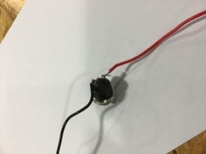
The process of soldering is pretty simple. After heating up the soldering iron, put the solder at the tip of the iron to let it melt, before putting the iron on the joint. After the spot is also heated up, apply solder onto somewhere near the joint and wait for it to melt. When the work is done, clean the tip. Though I have played around with it before, it seems my procedures were totally wrong. When I was soldering, I have been skipping the step on tinning the tip. What’s more, I have also been applying the solder right onto the joint or even the soldering tip. But finally, my partner and I have got the wires soldered securely soldered to the button. We even soldered to jump wires together.


Building the circuit was not complicated. Though when building the first circuit, we have encountered difficulties in reading the diagram, as the capacitator was a bit annoying. Therefore, we were confused about which socket should the wires and switches be connecting to. Another problem was the direction of the switches. We weren’t able to control the on and off of light using the switch, because we weren’t clear of the direction of the switch. After checking the information about the direction in the button, we made it work. But afterwards, we were able to get the first and second circuits working pretty quickly. The third circuit, however, involves more electrical components, so we were a little hesitated in wiring up. And my partner was not very familiar with the breadboard so that he almost connected two pins of an electronic component to the same row of the breadboard. After correcting his tiny mistake, we got our last circuit working as well. During the rest of the time, we used the potentiometer to make the tone of the speaker change while turning the potentiometer.
The brief description for the electronic components involved are down below:
BreakBoard: the board that has built-in wires, through which different electronic components can be connected more easily
Voltage Regulator: adjust the voltage flowing into the circuit
Speaker: a buzzer that can make noisy sounds
Push-Button switch: used to turn the circuit on and off
Arcade Button: works the same as the Push-Button switch, but there are less pins to connect
Capacitor: store electricity inside, which would feed back to the circuit
Resistor: to reduce the current in the circuit and prevent the components from burning out
LED: light up when connected in a circuit
Variable Resistor: a resistor that can change its ohms
12 volts power supply: the power for all components in the circuit
In general, technically speaking, the recitation last week wasn’t very complicated. The difficulties we encountered mostly resulted from our lacking dexterity.
Based on The Art of Interactivity, our circuits have very limited interactivity. The only possible interaction was pushing the switch and have the light lights up or the speaker makes a sound. It is almost in the same circumstances as opening the door of the fridge when the light in the fridge lights up, or a person avoids the branches falling from a tree.
When it comes to the relationship between physical computing and interactive design, physical computing acts as the empowerment of the interactive design idea in the artists’ mind. And in the process, the physical computing itself is only a tool and should be made accessible, in order to have the artist focus on creating completely.