Circuit 1: Doorbell
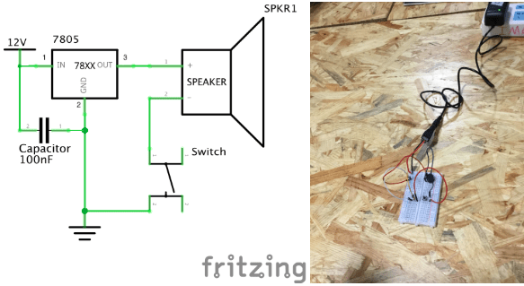
 List of Components: Wires, Power cord (12V), Breadboard, Capacitor (100nF), Voltage Regulator 78XX, Switch, Speaker,
- The wires are used to connect the components together.
- The power cord gives the breadboard power by connecting to electricity.
- The breadboard allowed us to make the electrical circuit.
- The capacitor holds excess electricity and stores it for future use. It does not dissipate energy and provides a consistent voltage which improves the performance of the circuit.
- The 78XX is a voltage regulator, it is included to produce a voltage that is positive relative to a common ground
- The switch turns the doorbell on.
- The speaker is included because it acts as a doorbell; it is the output.
The circuit worked the first time we built it, however, we forgot to include the voltage regulator. We were also unsure about the orientation of the switch. After a couple of rotations, we realized that it best bit between the gaps of the breadboard.
Circuit 2: Lamp

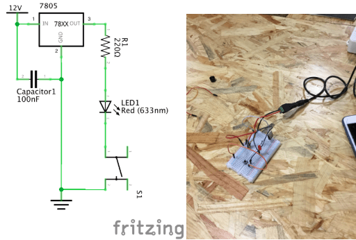
List of Components: Wires, Power cord (12V), Breadboard, Capacitor (100nF), Voltage Regulator 78XX, Switch, Resistor (22 Ohms), LED (633 nm)
- The wires are used to connect the components together.
- The power cord gives the breadboard power by connecting to electricity.
- The breadboard allowed us to make the electrical circuit.
- The capacitor holds excess electricity and stores it for future use. It does not dissipate energy and provides a consistent voltage which improves the performance of the circuit.
- The 78XX is a voltage regulator, it is included to produce a voltage that is positive relative to a common ground.
- The Switch turns the LED light on.
- The resistor is used to limit the amount of current going through the circuit. If a resistor is not included the LED can be destroyed
- The LED light lights up.
The LED light did not work the first time we set it up. This is because we did not know how to include the voltage regulator into the breadboard along with the resistor. We found it kind of confusing to put them together. We figured out that we had to use the resistor as the connector between the voltage regulator and the LED light as there would be not enough space on the board if we used wires.
Circuit 3: Dimmable Lamp
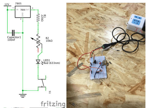
 List of Components: Wires, Power cord (12V), Breadboard, Capacitor (100nF), Voltage Regulator 78XX, Switch, Resistor (22 Ohms), LED (633 nm), Potentiometer (10k Ohms)
- The wires are used to connect the components together.
- The power cord gives the breadboard power by connecting to electricity.
- The breadboard allowed us to make the electrical circuit.
- The capacitor holdsexcess electricity and stores it for future use. It does not dissipate energy and provides a consistent voltage which improves the performance of the circuit.
- The 78XX is a voltage regulator, it is included to produce a voltage that is positive relative to a common ground.
- The Switch turns the LED light on.
- The resistor is used to limit the amount of current going through the circuit. If a resistor is not included the LED can be destroyed
- The LED light lights up.
- The Potentiometer is a multi-terminal resistor or a “voltage divider”. It is included to dim the light in the LED.
While building the dimmable lamp, we had trouble attaching the potentiometer to the breadboard. Since there were three pins attached to the potentiometer, we had trouble understanding what each pin was used for. The first time we built the dimmable lamp it did not work, only the LED turned on. After changing around the orientation of the wires and correcting connecting the LED and the resistor to the potentiometer, the LED successfully dimmed.
Reflection
Question 1: After reading The Art of Interactive Design, do you think that the circuits you build today include interactivity?
After reading The Art of Interactive Design, I believe that the circuits I built today included interactivity. Together, my partner Serene and I thought about how to connect the objects together to create a circuit. Whenever there was a problem, we examined the circuit, and listened to one another’s ideas about what could have went wrong. We also interacted with the objects that we had and created the output of sound and light out of small electrical components which is pretty fascinating.
Question 2: How can Interaction Design and Physical Computing be used to create Interactive Art? You can reference Zack Lieberman’s video or any other artist that you know.
Interaction design and physical computing could be used to create interactive art through the use of coding, technology, and physical art. In Zack Lieberman’s video, he created a Eyewriter which ultimately lead to an type of interactive art. The idea behind the Eyewriter was interactive between the patient and the world outside of the hospital creating a magical performance for the patient and the people outside. With interactive design and physical computing, the power of coding, technology and a purpose for the creation, the art, design, and technology together merge into interactive art.