Circuit 1: Fade
- Components: 1) an Arduino Uno : a physical computer to drive and make command to the whole circuit
2) a Breadboard: a basic stage for building the circuit
3) a 220 ohm resistors: to limit the volt distributed on the LED to ensure it will not broke
5) a LED : can be lighten and make the command of the Arduino Uno observable
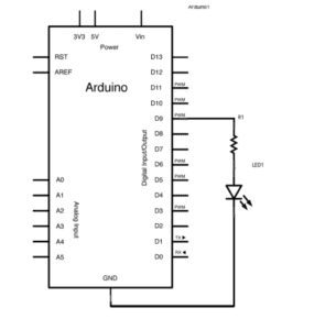
2. Diagram:
3. Pictures and video of the completed circuit:
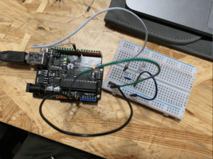
4. The process of building the circuit: We first connect the 5V and ground on the Arduino to the breadboard, then we connect the resistor and the LED to the pin 9. The circuit worked good with the drive of the coding, as you can see that the LED was blinking in the video before.
Circuit 2: toneMelody
- Components: 1) an Arduino Uno : a physical computer to drive and make command to the whole circuit
2) a Breadboard: a basic stage for building the circuit
3) a buzzer: make sound to testify the circuit and make the code observable
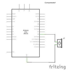
2. Diagram:
3. Pictures and video of the completed circuit:
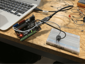
4. The process of building the circuit: The connection for this circuit is quite simple, we just connected the positive of the buzzer to the pin 8 ,and its negative to the ground. The circuit worked well as you can see in the video.
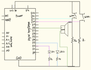
Circuit 3: Speed Game
- Components: 1) an Arduino Uno : a physical computer to drive and make command to the whole circuit
2) a Breadboard: a basic stage for building the circuit
3) two LEDs: to make the result of the match observable
4) a speaker: make signal sound as time ends
5) two pushbuttons: a major input in this circuit for the two participants in this game. The game is tested by weighing which participant click the button faster.
6) two 220ohm resistors: limit the volt on the LED for protection
7) two 10ohm resistors: limit the volt on the pushbuttons
2. Diagram:
3. Pictures and video of the completed circuit:
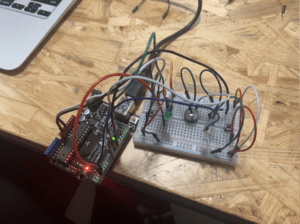
4. The process of building the circuit: This is quite complicated circuit. We built it with the help of the online resources. While strictly follow the guidance, the circuit still couldn’t work. We checked the circuit once again and found out that a wire between the LED 1 and the R3 was broken. So we changed this wire to another and the circuit worked well as you can see in the video. What a tensive game!
Answer to the Questions:
- In my daily life I enjoy the convenience of the technology. I interact with the devices which contain a lot of technology mostly by using them, inputing what I want (tap, swipe. etc) and receiving information from them. I rely on the coding written by those engineers. When I was building the circuit, however, I change my perspective as a consumer of the technology to an experiencer and creator of technology. For me, interaction means the mutual communication between two entities.
- I’ll make a device that the LED inside can light in different way adapting to the music. I am gonna put it in somewhere of the campus so that we can have a place for partying !!(Just kidding, I’m not a fan of parties lol)