During our first recitation, we worked on soldering different wires together as well as constructing three basic circuits in order to better understand the functions of different electrical components.
Components:
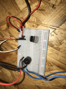
Breadboard: A layout of conductive terminals that facilitates the creation of the circuit by providing a consistent cable design.
12 Volt Power Supply: Plugs into an electrical outlet and provides the electrical source for the circuit.
LM7805 Voltage Regulator: Maintains a constant voltage level so the buzzer and LED can operate as efficiently as possible.
100 nF Capacitor: Assists in the functioning of the voltage regulator by acting as storage for any extra voltage that exits the regulator.
Arcade Button: Allows one to control whether or not electricity passes through the circuit by pressing the button.
Buzzer: The output of the circuit that uses electricity to produce a buzzing sound whenever the arcade button is pressed.
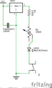
220-ohm Resistor: Adds resistance to the circuit in order to decrease the voltage and keep the LED stable.
LED: The output of the circuit that uses electricity to emit light.
10K ohm Variable Resistor: A resistor whose resistance can be altered by turning a knob. It allows the interactor to adjust the brightness of the LED to their desire.
Jumper Cables: Cables that connect to the terminals in the breadboard and assist in the creation of the circuits.
Barrel Jack: Converts the cable of the power supply to make it compatible with the breadboard.
Multimeter: Measures voltage, current, and resistance. We used it in order to find the correct resistor for each circuit.
Push-Button Switch: Gives interactor the power to choose when to let the current flow.
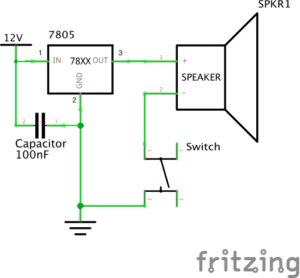
Circuit 1: Door Bell
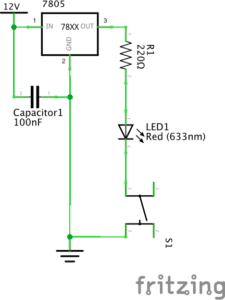
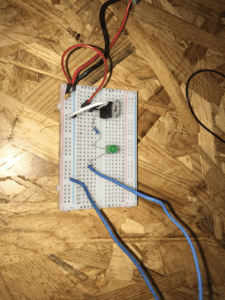
Circuit 2: Lamp
Circuit 3: Dimmable Lamp
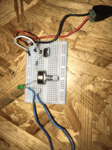
Building Process:
Soldering:
The process of soldering the two wires to the arcade button was a very rewarding and exciting experience. It was difficult to maneuver the positioning of the soldering iron with the wires to correctly connect them to the arcade button but with great teammate coordination, we were able to quickly complete the challenge.
-Circuit 1:
Building the first circuit was the most difficult as we had to learn how to work with the layout of the breadboard. We encountered problems because we were not familiar with the function of each piece, but once we had referred to the recitation notes, we were able to identify each piece in order to correctly place it in the breadboard. Once we had identified all the pieces and placed them in the correct circuit, we ran into another issue: the buzzer would not buzz. We then contacted the teaching fellows for assistance as our circuit was entirely correct but would not work. After switching out some of the pieces to make sure they were not causing the circuit to fail, the buzzer then worked!
-Circuit 2:
Building the second circuit proved to be a lot smoother as we were more familiar with each piece’s function in the circuit as well as the layout of the breadboard. The only difference between circuit 1 and circuit 2 is that we had to replace the buzzer with an LED and we also had to add a resistor to tone down the voltage in order that the LED does not overheat. Because we could reuse a lot of the previous circuit, we did not run into the same equipment and layout issues as the previous circuit.
Circuit 3:
We also ran into similar problems with the last circuit. It proved to be more difficult than circuit 2, but easier than the first. The difference between circuit 2 and 3 is that we simply had to add the 10K ohm variable resistor so that we could adjust the brightness of the LED to our desire. Once we had added this resistor, the circuit ran into a problem as the LED would not turn on. So once again we asked the teaching fellow to assist us with the issue as we believed the layout of our circuit was correct. The teaching fellow then checked all parts of our circuit and it seemed to be correct, so then we deduced that the problem again lied in the reliability of the materials in our circuit. So then we arranged a few of the wires and replaced the 10k ohm variable resistor and the circuit started working! Once the circuit functioned we were able to turn the LED on as well as adjust the brightness.
Things I Learned:
During the process of building these first few circuits, I learned quite a few important things about the design process. One is that in order to learn and to progress with the goal that you are trying to accomplish, you can’t see failure as a hindrance. It is in fact just as important as any success, and in fact probably even more important because our failures teach us lessons that allow us to continue progressing. There were a couple of issues in the design process as stated above, but the recognition and then resolution of these issues helped me and my partner learn a lot more than we would have otherwise.
Question 1:
I believe that every circuit created in this recitation utilized some form of interaction. As stated in, The Art of Interactive Design, interaction is not a black and white scenario, but rather a continuous issue with many degrees. Interaction can be defined as a cyclical process where one actor performs one task, and another reacts, which then in response the original actor responds again. This is true within all of our circuits as they required our own participation as well as the circuits’ participation in order to perform the correct tasks. We interacted with circuit one by turning on the buzzer with the arcade switch, we interacted with circuit two by turning on the LED, and we also interacted with circuit three by adjusting the variable resistor in order to control the brightness of the LED. In all of these scenarios, my partner and I interacted with the circuit, and in response, the circuit provided us with a physical output in which we then reacted to. I also believe the design process itself is very interactive, as we design the circuit, and it then responds to us by performing the desired output or not. In turn, we either enjoy our success or use the lack of output to continue to manipulate the circuit.
Question 2:
I believe that art is any kind of physical manifestation that is able to draw emotion from us. So from my personal definition of art, interaction design and physical computing are most definitely mediums that can be used to create interactive art. For example, The EyeWriter, mentioned in Zach Lieberman: Interactive Art, is a type of wearable technology that allows someone to draw digital images with the movement of their eyes. This technology is a form of interactive art because it allowed a paralyzed graffiti artist to continue his passion even if he no longer had control of the rest of his body. Art is simply a manifestation that permits us to think and feel and if that art also happens to be interactive, then I believe it has an even greater ability to draw us in and provide us with personal meaning. So because the EyeWriter allowed someone to pursue their passions that would have rather been hindered, of course, we can connect the disciplines of computing and design to interactive art.