Lab Date: Feb 15, 2019
Instructor: Marcela
Lab Partner: Julie Huang
Circuit One:
Circuit One Components:
1x Buzzer: Creates beeping sound when there is an electric current flow.
1x 100 nF Capacitor: Acts as a power supply
1x Push Button Switch: Starts or stop connection in the electric circuit
1x LM7805 Voltage Regulator: To regulate and maintain a voltage level. In this circuit it helped transfer 12V voltage level to 5V voltage level
1x Breadboard: A construction base for connecting components
1x 12 Voltage Power Supply: Acts as a stable power source
1x Barrel Jack: Used to connect extra low voltage devices to external electricity.
Jumper Cables: To connect components and pieces.
Where is the power?
While connecting the jumper cables to the breadboard, Instructor Nick spotted a mistake about our circuit. He pointed out the jumper cables that are connected to provide power for the rows and we must connect other jumper cables to those specific rows to create a circuit.
Circuit Two:
Circuit Two Components:
1x Breadboard: A construction base for connecting components.
1x LM7805 Voltage Regulator: To regulate and maintain a voltage level. In this circuit, it helped transfer 12V voltage level to 5V voltage level.
1x Push Button Switch: Starts or stop connection in the electric circuit.
1x Arcade Button: A button that had to be soldered but is able to connect the whole circuit when pressed.
1x 220-ohm Resistor: To reduce current flow
1x LED: Omits light when connected to a power source
1x Barrel Jack: Used to connect extra-low voltage devices to external electricity.
Jumper Cables: To connect components and pieces.
1x nF (0.1uF) Capacitor: To store electrical energy
1x 12V power supply: Provides power source
1x Multimeter: Measures voltage, resistance, and current.
How do you efficiently use the breadboard?
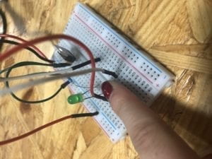
While trying to put circuit two together, we realize the buzzer occupied quite a lot of breadboard space. Therefore my partner and I, with the help of the professors, decided to plant the buzzer on two different sections of the motherboard (as indicated on the picture above).
Circuit Three:

Circuit Three Components:
1x Breadboard: A construction base for connecting components.
1x LM7805 Voltage Regulator: To regulate and maintain a voltage level. In this circuit, it helped transfer 12V voltage level to 5V voltage level.
1x Push Button Switch: A switch that is able to connect the whole circuit when pressed.
1x 220-ohm Resistor: To reduce current flow
1x 10k oHm Variable Resistor (Potentiometer): To change resistance in a closed circuit.
1x LED: Omits light when connected to a power source.
1x 100 nF (0.1uF) Capacitor: Stores electrical energy.
1x 12 Volt power supply: Provides power source
1x Barrel Jack: Used to connect extra-low voltage devices to external electricity.
Jumper Cables: To connect components and pieces.
1x Multimeter: Measures voltage, resistance, and current.
How can we organize our breadboard?
While trying to attempt circuit three, my partner and I quickly realize it was the most complex out of all the challenges. Circuit three required the most jumper cables and cables are confusing and easy to tangle up. Therefore we decided to use different colored cables and spread out the cables in order to make the circuit three easier.
Reflection:
I did not encounter a huge problem trying to put the pieces together for the different circuits. Instead, my partner and I had a more difficult time trying to envision how we can place the components together to achieve the goal. As it is our first time trying to understand how electricity works, we had to consult the professors regarding how we can work out the diagrams. However after we had a general idea/pattern, we learned the ideas and employed it onto the circuits following circuit one.
Answers:
Question One:
After reading the text, I realize the circuits we built today included interactivity as all circuits included an input, an output, and a process. Although these circuits can be considered a lower degree of interaction, it still took two parties to create a reaction. One party is the circuit and the other party being the conductors (my partner and I) pressing a switch. Therefore, I believe our circuits do include interactivity, according to the definition found in the article.
Question Two:
After building the three circuits, I believe we were introduced to the interactive design component but I feel like physical computing is vital to being able to create Interactive Art. Physical computing and interaction design both involve building interactive software that consists of a stimulus and a response. By creating interactive software that can provide a different response, it attracts users to attempt different stimulus. Especially with technology advancements, the potential templates for interactive art is plentiful and the future is broad.