Overview
For this project, my partner and I built three different circuits and then we were taught how to solder. The first circuit was a “door bell”, which was essentially just a speaker that constantly beeped. The second circuit was a lamp, or a light that turned on at the push of a button. The third circuit was almost the same as the second, except that it included a variable resistor in order to make the light dimmable. After building the circuits, my partner and I were taught how to solder so that we could make a button to replace the button that was already in the circuit, which we borrowed from the lab. We were able to complete all the tasks successfully (with some help from the professors).
Materials:
- 1 Breadboard: holds components of circuit
- 1 Voltage Regulator: regulates voltage
- 1 Speaker: makes noise
- 1 Capacitor: stores and discharges electrical energy
- 1 Switch (button): completes the circuit at the will of the user (human-activated)
- Replaced by arcade button from soldering workshop
- 12 volt power supply: provides power to the circuit
- 1 220Ω Resistor: regulates the flow of electrical current so as not to damage other components like the LED
- 1 10KΩ Resistor
- 1 Variable Resistor: a resistor in which the user can control the voltage flowing through the circuit
- 1 LED: lights up
- Several Wires: used to connect components on different parts of the breadboard
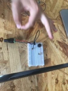
Circuit #1: Doorbell

Image from Interaction Lab Website
The first circuit required the voltage regulator, the capacitor, the button, the speaker, several wires, and of course, the power source. The voltage regulator was the first component that we put into the breadboard, but we were confused as to which pins on the voltage regulator connected to the other components. Since neither me nor my partner have experience in making circuits, we needed some help from the instructors to make this circuit work. However, after the instructor demonstrated where the pins on each component of the circuit were supposed to go, we quickly constructed the circuit correctly. She showed us how to make connections to the voltage regulator, and from there we were able to construct the rest of the circuit ourselves.

Circuit #2: Lamp

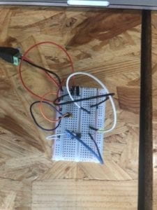
The second circuit required the voltage regulator, the capacitor, the button, the LED, several wires, and a resistor. The circuit did not differ very much from the first circuit, so we were able to preserve most of the components that we used before. Besides having to be reminded that the resistor is not polar, my partner and I did not have any trouble constructing this circuit.

Circuit #3: Dimmable Lamp

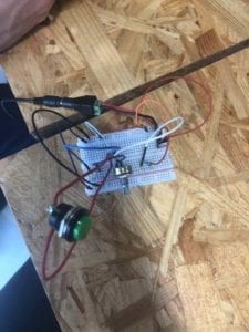
The third circuit required the voltage regulator, the capacitor, the button, the LED, several wires, a resistor, and a variable resistor. Although this circuit was nearly identical to the previous one, save for the variable resistor, this circuit gave my partner and I the most trouble. Some of the connections we made to the variable resistor were incorrect since we misread the diagram, but an instructor helped us fix it. We also replaced the switch in this circuit with the arcade button that we soldered.

Soldering Workshop
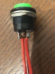
Between the second and third circuit, my parter and I went to room 826 to learn how to solder. After the soldering guns heated, the instructor showed us how to melt the solder onto the components that we wanted to connect. My partner soldered the first wire to the arcade button and I soldered the second one. Initially, it wasn’t melting at all, but the instructor noticed that my partner was using the wrong part of the metal tip. After he corrected us, we were able to make the connections and use the button in our final circuit.

Question 1:
Interactivity is the mutual action of two different “actors”. I do not think the first circuit was interactive at all, though I do think the second and third circuits were. In the first circuit, there were no actors. After my partner and I built the circuit, it continued to function without the intervention of any actors, human or otherwise. On the other hand, the second circuit required two actors: the human user and the switch. The human interacts with the switch, which results in the LED lighting up. When the human released the switch, the light would turn off. Likewise, in the third circuit, the brightness of the LED was determined by interaction between the human user and the variable resistor.
Question 2:
One example from Zach Lieberman’s video that I found particularly interesting was the EyeWriter. That seemed like a practical use of interactive technology that directly benefits people. That isn’t to say that his other projects were not interactive, but they seemed more like methodological experiments in comparison to the EyeWriter. To answer the question, I think that the best use of interactive technology in art is that which facilitates the creation of art, as in the case of the EyeWriter, rather than those which force the creation of art, as in the case of the font created by driving a car under a camera.
great documentation Jackson!
just remember for the next posts to add the questions before your answers.