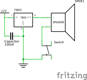
Circuit 1-Door Bell
Components:
1*Breadboard: A base for connecting components
1*LM7805 Voltage Regulator: To regulate and maintain a constant voltage level which is suitable for the circuit
1*Push-Button Switch: Able to connect the whole circuit when it is pressed
1*Buzzer: To output an audio signal
1*100 nF (0.1uF) Capacitor: To store electrical energy
1*12 volt power supply: To provide power source
1*Barrel Jack: An electrical connector for supplying direct current
Jumper Cables (Hook-up Wires): To connect components
The Diagram
The Building Process and Problems We met
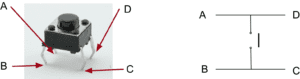
How to connect the switch???
When we were connecting the switch, we found it difficult to distinguish which two feet to choose. We expected there should be different length of the feet so that we could identify the anode and the cathode, but all the four feet seemed the same. Out of ideas, we turned to Nick for help. He then told us the way of connecting the switch was to know that foot A and D are always connected. Same with foot B and C. Therefore, only connecting either A or D to either B or C can be counted as successful connecting.
Where is the voltage regulator???
We first built the circuit without the voltage regulator, because we misinterpret the symbol for the voltage regulator as the power source. Since the circuit still worked well, we did not notice this mistake. However, Leon came by and pointed out that we should add the voltage regulator to the circuit in case the voltage level could be too high for it. Therefore, we corrected our circuit and it worked again.
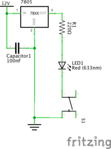
Circuit 2-Lamp
Components:
1*Breadboard: A base for connecting components
1*LM7805 Voltage Regulator: To regulate and maintain a constant voltage level which is suitable for the circuit
1*Push-Button Switch: Able to connect the whole circuit when it is pressed
1* Arcade Button: Able to connect the whole circuit when it is pressed, but needed to be soldered
1*220 ohm Resistor: To reduce current flow
1*LED: Able to emit light when connected to the power source
1*100 nF (0.1uF) Capacitor: To store electrical energy
1*12 volt power supply: To provide power source
1*Barrel Jack: An electrical connector for supplying direct current
Jumper Cables (Hook-up Wires): To connect components
1*Multimeter: To measure voltage, current and resistance
The Diagram:
The Building Process and Problems We met
Why the light was not on???
We built the circuit exactly as what the diagram told us, however, the LED just refused to emit light. We checked every connecting point without recognizing any problem. At last, we asked Nick about this situation. As he suggested, we used the multimeter to measure the resistance and surprisingly figured out that we connected the wrong resistor, which was only 10 Ω. We immediately altered the resistor and the light went on.
We replaced the switch!
After soldering the arcade button, we decided to replace the push-button switch. The process was quite simple. And we found that there was no need to take down the push-button switch while connecting the arcade button.
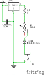
Circuit 3-Dimmable Lamp
Components
1*Breadboard: A base for connecting components
1*LM7805 Voltage Regulator: To regulate and maintain a constant voltage level which is suitable for the circuit
1*Push-Button Switch: Able to connect the whole circuit when it is pressed
1*220 ohm Resistor: To reduce current flow
1*10K ohm Variable Resistor (Potentiometer): To change the resistance in a close circuit
1*LED: Able to emit light when connected to the power source
1*100 nF (0.1uF) Capacitor: To store electrical energy
1*12 volt power supply: To provide power source
1*Barrel Jack: An electrical connector for supplying direct current
Jumper Cables (Hook-up Wires): To connect components
1*Multimeter: To measure voltage, current and resistance
The Diagram
The Building Process and Problems We met
Why the light was not on again???
Again, we followed the diagram but found the light was not on in a close circuit. Based on experience, we checked the resistor and were sure it was the right one. What confused us was that the first time we pressed the button, the light was on perfectly. However, every time we pressed the button, the light became dimmer until it vanished completely. We were afraid that we might have burnt the light for some unknown reason, so we asked Marcella for help. She checked our circuit and told us we connected the variable resistor in a wrong way.
As the picture above shows, we then connected the left and the middle terminals into the circuits. It turned out that the circuit worked well and we did not burn the LED.
Reflection
The diagrams were simple enough to understand and the building process was quite easy. However, we still met problems. After the solutions were figured out, I reflected on why these problems have come up. One reason was that we did not read the instructions carefully enough to clearly know how to connect every components. Another reason was that we were not familiar with the breadboard, which made us panic easily every time there existed problems. For solutions, I found a helpful piece of reading in the instructions for this recitation called “Getting Started in Electronics”, through which I could access detailed basic knowledge of electronics.
Answers to the questions
Question 1:
After reading The Art of Interactive Design, do you think that the circuits you built today include interactivity? Please explain your answer.
According to The Art of Interactive Design, there is no absolute answer to the question of whether an object is interactive. Instead, the degree of interactivity varies subjectively. Therefore, the circuits I built in the recitation can be regarded as interactive. As the author defines, interactivity happens when actors listen, think and speak, which can also be defined academically as input, process and output (5). In this case, one actor is the circuit while the other is the person who presses the button. During the process of interaction, the circuit listens (to the action of pressing the button), thinks (through processing the action), and speaks (by turning on the light or the speaker). Therefore, there did exist interaction.
Question 2:
How can Interaction Design and Physical Computing be used to create Interactive Art? You can reference Zack Lieberman’s video or any other artist that you know .
Interaction Design functions as a mediate for its objects to create Art, and Physical Computing can be used as a tool to achieve Interaction Design. In Zack Lieberman’s video, he launched three artistic practices, respectively called “Drawn”, “iq Font” and ” Eye-writer”, with his software skill. Through these practices, his softwares allow people to create Art and expresses with low barrier. That is how Interaction Design and Physical Computing can be combined to create Interactive Art.