Overview
Overall, the circuits were interesting to test out as each got increasingly difficult. The first circuit, the fade, was the easiest and the last circuit was the most difficult because of the amount of connecting wires. We did not have time to finish connecting the fourth circuit.
Circuit 1 Fade:
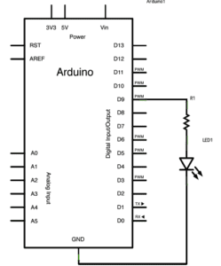
This circuit overall was not too difficult to complete. We connected the LED to ground and to the 220 Ohms resistor which connected to digital pin 9 (according to the code for fading). The light faded almost blinking repeatedly.
Video of working circuit:
Circuit 2 toneMelody:
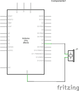
This circuit also was not too difficult and we did not run into any major issues. We connected the buzzer to digital pin 8 and ground. The speaker would play a preset melody.
Video of working Circuit:
Circuit 3 Speed game:
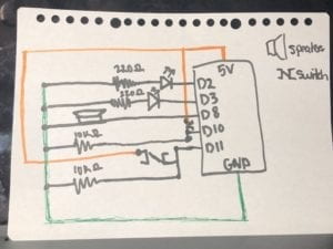
This circuit was the most difficult only because there were so many wires connecting many components. If you missed a connection it was difficult to quickly find the wiring error because you had to check every single wire connection. We especially found issue with one arcade button as it was not soldered very well and its connection was a bit spotty. For this circuit we connected to 5 different pins, two connecting to the LEDs, two connecting to the buttons, and one connecting to the speaker. There were also two 10 Ohms resistors that are connected to the buttons and two 220 Ohms resistors that are connected to the LEDs.
Video of working circuit:
Questions
Question 1:
Between my personal understanding of interaction and the one I read in Physical Computing, I believe interaction is defined by an input, processing, and output. There are two actors in each interaction, and an input is provided, interpreted or understood, and then responded to with some sort of output based on the input provided. In the passage Physical Computing, interactions was given the analogy of listening(input), thinking(processing), and speaking (output). One actor listens to the other taking in the input, thinks about what they said and what the input means, interpreting how to respond, and then finally responds by speaking bact to them based on their cognition.
Question 2:
We used the 10K resistor to not overload the circuit. In addition, based on some external research of pull-up and pull-down resistors, according to “Pull-up/ Pull-down resistors- explained with calculations” and “Why use resistors with push button or switch with Arduino”, pull-up or pull-down resistors can be used to higher or lower resistance. With digital inputs like a switch turning it on or off (1s and 0s), without a resistor there is an inbetween section of voltage that is uncertain whether it would be assigned a 1/0 or on/off. This is due to noise or interference that surrounds us from other devices. The resistor closes the gap of uncertainty, pulling the voltage in this case down to ensure the switch is either on/off or 1/0.
Question 3:
If I had 100,000 LED lights and the coding and wiring experience to complete this, I would want to make a billboard-sized arcade-style pacman game that could be played in some public space by anyone. The lights at different brightness and colors would light up a for the most part non-changing background maze to play the game, and with a joystick like controller the player could control a small group of lights that would move (by blinking on and off) to show their packpam and another moving group of lights would be different monsters and or collectables for pacman. It would be pretty complex to upload the gaming code to the light board, but entertaining for not just the players also the public.