Introduction:
During the first recitation I experienced many new processes and problem solving opportunities, including building various circuits and soldering.
Circuit 1:

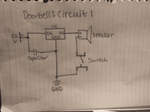
The doorbell circuit diagram included a 12V battery, or in our case a power source that is connected to an outlet. The 12V battery is the source of electricity to the entire circuit, providing the electrons that will run throughout the closed circuit. The 12V contained a negative and positive wire, the positive to provide the flow of electrons and the negative wire will connect to other components of the circuit that need to be grounded. The capacitor connects to the positive wire of the 12V and also to the negative 12V wire to ground it. The capacitor retains and stores electrical energy. The voltage regulator has the connecting components: an input, output, and grounding component. The input metal prong connects to the positive wire from the 12V, the output metal prong connects to the speaker, and the grounding metal prong connects to the negative wire from the 12V to ground it along with the capacitor. The voltage regulator is a mechanism intended to maintain the circuit’s voltage at a constant voltage. The speaker connects to the output prong of the voltage regulator and also connects to the switch. The speaker is the mechanism that produces sound when the circuit is closed and the electrons flow through the circuit, powering the speaker. The switch connects both to the speaker and to the negative wire of the 12V power source to ground the switch. The switch (in our case a button) will close the circuit when the switch is closed and leave the circuit open when the switch is open. As long as the power source is connected the switch determines whether or not the circuit is closed and electrons can flow throughout the circuit to power the speaker. With the doorbell circuit we ran into issues with the orientation of the switch as the connecting wires must be precise. We also ran into an issue with the switch not reaching the bottom of the breadboard the metal prongs were bent too much and therefore did not fit easily into their proper holes. For this circuit it made the connection of the speaker spotty and therefore even though the switch was closed when we completed the circuit the sound went in and out because the prongs did not connect to the bottom of the breadboard. For the next circuits we tried to ensure better connection between each component and the breadboard. We also switched to the arcade switch for the final two circuits because it connected better to our breadboard.
Circuit 2: The Lamp

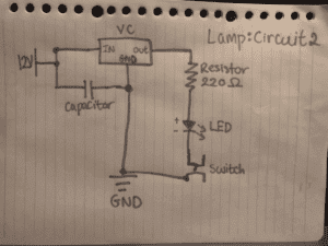
For the second circuit, the lamp circuit ,we used the base and similar structure of the circuit and altered the parts in the circuit that were different, specifically adding the resistor, the LED, and the arcade switch (for better connection). The power source, voltage regulator, and resistor all stayed the same regarding orientation on the breadboard. Differing from the Doorbell circuit, we added a resistor to the circuit connecting it to the output of the voltage resistor. We also connected the resistor to the LED’s positive wire (the longer wire end). The 220 Ohms resistor reduces the voltage to control the flow of electrons to the LED which requires less voltage the power source provides. The LED is a light with positive and negative wires. The LED lights up when the circuit is closed as the flow of electrons powers it. The arcade switch was put in place as the normal switch but we did not dim the light using the different settings of the arcade switch. This switch took a long time for us to build because we were interrupted to take the soldering workshop, which for our groups took much time because our machine was not hot enough to start and therefore did not heat up the metal enough to join the switch and the wire. With this circuit we ran into orientation issues on which wire to connect to which prong of the voltage regulator. To solve this problem we consulted the images at the bottom of the instructions that had a key for how the voltage regulator should be connected.
Circuit 3: The Dimmer Lamp

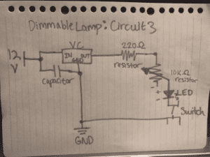
The last circuit was our Dimmer Lamp circuit. The circuit was similar to the previous lamp circuit but also included a second resistor, 10 Ohms, the potentiometer. The potentiometer is a resistor that reduces the voltage of the circuit through its three terminal mechanisms. One prong is connected to the first resistor, the second prong is connected LED, and the third prong is grounded. At first we ran into trouble with which prong to connect to which component but the diagram at the bottom of the recitation instructions outlined the correct method, helping us fix our orientation issues.
Process and Problems:
All the circuits worked. The doorbell circuit worked on the first try. Both the dimmer circuit and the lamp circuit required a bit of trial and error, as we fixed the resistor’s position in the lamp circuit and the potentiometer’s connections on the dimmer circuit. Our main difficulties with the circuits where with our switch not connecting fill to the breadboard, which we fixed by changing the switch we used for the second two circuits. The orientation of certain components on our breadboard was also challenging, as some components like the potentiometer only worked with certain orientation and connections of certain metal prongs to the LED, resistor, and grounding. In addition to a few minor procedural issues we faced in the construction process, as we built the last circuit (the dimmer), we were only able to test one level on the arcade switch. Our circuit did work in theory but we were only able to test one of the three brightness, partially for time constraints, and partially because we could not get the switch to change brightness.
Question 1:
The circuit would, in theory, be considered interactive as there was an interaction between the person pressing the button and the switch closing the circuit to perform a task, whether that be lighting up or producing a sound. The original initiating action is the human pressing the button. As a reaction to the button being pressed the switch closes the circuit, which intern produces an output of sound or light. In the “What exactly is Interaction?” reading, the author mentions different degrees of interaction (6). As a circuit controlled by a button/arcade button, the circuit does have some degree of interactivity as two interacting parties (the circuit and human) both have actions and reactions to the other party, but they are not as complex interaction as two humans would have, being able to respond in different manners based on their best judgment of the situation.
Question 2:
Daniel Rozin’s wooden mirror is a more complex interaction between a human and the mirror itself requiring multiple steps to perform the interaction. The human has some sort of movement and the camera or sensors of the mirror record those movements, sending a signal to the different motors powering each wood panel. As a result of that signal, the motors move to change the angle of the wood and allow for different values to show the image being mirrored. The light reflects off of different panels of angled wood to form different values and make the human image. Interactive design is used throughout the wooden mirror, especially considering the sensors and cameras that map the image of the human and then translate those signals so the motors on each wooden block can move and form the human image based on light reflection.
Physical computing uses software and hardware to create interactive systems, which is how many interactive art projects program their project combining coding and software with hardware, tangible microcontrollers and devices connecting the software and instructions from coding with the physical controllers that control the motors just like in the wooden mirror. The software instructs the project to take in and process the image from the sensors and camera converting that into data and then instructing the tangible motors and microcontrollers to signal movement of each wooden block.