Lab Time:9/20/2019
Partner:Andrew Xie
Components Used:
From Arduino Kit:
-
- 1 * Arduino Uno
- 1 * USB A to B cable
- 1 * breadboard
- 1 * buzzer
- 2 * LEDs
- 2 * 220 ohm resistors
- 2 * 10K ohm resistors
- 2 * pushbuttons
- A handful of jumper cables
From cart:
-
- 2 * arcade buttons
- 1 * Multimeter (optional)
Lab Content:
-
- Fading Lights
- Tone Melody
- Speed Game
Detailed Description:
Fading Lights
This project used the Code from Arduino>File>Examples>03.Analog>Fading. And below is the schematic graph of the circuit.

Though we thought the first one should be pretty easy, but in fact it’s just this one project that takes us the longest time.

As you can see, the LED light was simply flashing rather than fading. The first thing occured to us was there must be something wrong with our code. So we checked our code only to find no BUGs. And we asked the instructors for help and it turned out that the circuit connection had no problems too.
When we didn’t know what to do, Eric stopped by, checked our Arduino borad and pointed out a subtle error:
The reason why we’ve got a problem is that the pin 13 was connected as the output terminal and it can only control basic 0/1 or HIGH/LOW information (digitalWrite), and to control the dimness, thus we need to use a pin to give analogWrite results. Finally, we change the output end to Pin 9 and it was a success in getting the fading effect on the led lights.
Tone Melody
This project used the Code from Arduino>File>Examples>02.Digital>toneMelody. And below is the schematic graph of the circuit.

This part was pretty easy, and with the help of sample code, we quickly built the circuit and tested. It turned out that we made it.
Speed Game
This project used the Code from https://www.tinkercad.com/things/6MzvN5rlZlr-race-the-led-spring19.
And below is the schematic graph of the circuit.
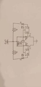
The third Circuit was very challenging for me and my partner. Because we thought that the installation method according to the design drawing would make the wiring messy and ugly, we redesigned it to make the circuit more beautiful in a symmetrical way, which, of course, cost us more time.


Due to time limitation, we did not build Circuit 4, but we found other team members to play the game together.

Question 1:
To be honest, I’m using all kinds of interactive technology to type in these words for my documentation: from keyboard, monitor to CPU, all of them are a reflection of interative technology. We give something as an input and it returns us with some results. As for the circuits we build, we offer some changes (like the rotation of variable resistors) and it feeds back some changes (like tone/brightness changing or victorious ringbells).
Question 2:
We use the 10K resistor with the push button to keep the control part circuit under protection and won’t encounter any short-circuit problems. If we use a resistor with lower resistance, there would be a great chance that once we leave the switch on accidentally and connect the current source, it would become a short-circuit so we must use a resistor with great resistance like 10K.
Question 3:
I would make use of them as general facilities in some poverty-stricken areas in China, where the lack of brightness (like traffic lights, streetlamps and family-use lamps) limit people’s life qualities in a great way.