Introduction
This is my first documentation of the semester. In the first recitation we were asked to do both soldering and circuits building. After doing the soldering, my partner and I were able to complete two of the three circuits in recitation. I completed the third circuit after class with another partner.
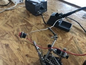
Soldering
We successfully stuck the first wire with the button through the join. But when we tried to do it a second time, we did not control the soldering iron so well and melted the join down…
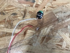
So we had to find a new button and start all over again. This time with more experience we were able to do it successfully. I think the key is to find the precise position to place the soldering iron.
Circuit 1: Door Bell
Components:
- 1 * Breadboard
- 1 * LM7805 Voltage Regulator
- 1 * Buzzer (the door bell in this case)
- 1 * Push-Button Switch (to control when the door bell rings)
- 1 * 100 nF (0.1uF) Capacitor
- 1 * 12 volt power supply
- 1 * Barrel Jack
- Several Jumper Cables (Hook-up Wires)

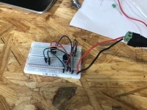
Following the diagram we put all the components on the breadboard and connected them with the hook-up wires. At first we are not accustomed to experimenting with all that stuff (for example, we had no idea how a breadboard works…), so we asked for a fellow’s help. With her introduction we were able to finish our first task. And the door bell works: (video below by my partner Ruben)
Circuit 2: Lamp
Components:
- 1 * Breadboard
- 1 * LM7805 Voltage Regulator
- 1 * Push-Button Switch
- 1 * 220 ohm Resistor
- 1 * LED (in this case the lamp)
- 1 * 100 nF (0.1uF) Capacitor
- 1 * 12 volt power supply
- 1 * Barrel Jack
- 1 * Multimeter (to measure the resistor)
- Several Jumper Cables (Hook-up Wires)

At first it did not work because we had the wires wrong. The wires look messy, so we started all over again.
(video below by my partner Ruben)
After reorganizing the wires we were able to make it work. Our old way of organizing the wires is a bit confusing because the wires cross each other and is not so easy to identify. In the second attempt we made them more organized and easy to follow. And the lamp works: (video below by my partner Ruben)
Circuit 3: Dimmable Lamp
Components:
- 1 * Breadboard
- 1 * LM7805 Voltage Regulator
- 1 * Push-Button Switch
- 1 * 220 ohm Resistor
- 1 * 10K ohm Variable Resistor (Potentiometer)
- 1 * LED
- 1 * 100 nF (0.1uF) Capacitor
- 1 * 12 volt power supply
- 1 * Barrel Jack
- 1 * Multimeter
- Several Jumper Cables (Hook-up Wires)

After class, I collaborated with another partner to complete circuit 3. With the variable resistor circuit 3 looks more complicated than the previous ones, especially with all the wires flying around. This time I was more experienced, but I made a mistake in my first attempt. When looking at the diagram, I did not pay attention to the direction of the current when it was flowing through the LED. With my partner’s help I checked the diagram again and realized that I needed to turn the LED around. And after doing that, the lamp is on when I click the switch.
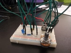
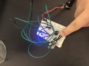
When I control the variable resistor for different resistance, the lamp becomes a dimmable lamp! (video below by my partner Anica)
Reflection and Evaluation:
After the first recitation, I got my hands dirty and got to know how the circuits actually work on a breadboard. This deepens my understanding of those electronic concepts learned from class and and the process is actually pretty fun and challenging. Particularly, I am now able to match the real electronic and its English name and its visual image. These improvements aside, I think I also need to pay more attention to the organization of a circuit and the flow of the current so that my circuit building process would be more smooth.
Answer to Question 1:
As the reading suggests, interaction is “a cyclic process in which two actors alternately listen, think, and speak.”The key point here is that interaction involves two actors. Based on this definition, when I turn on the switch or change the variable resistor, the door bell goes off or the lamp shines, that can count as interactivity.
Answer to Question 2:
Zach Lieberman sees software and technology not as the end, but as the means of creating magic things that concern interaction and communication. His design EyeWriter helped a paralyzed man draw pictures with his eyes and projected his drawings onto the walls in downtown Los Angelos. Zach’s interactive design can be called “interactive art” because it really involves a higher end and is expressed in such an artistic fashion.
this is great documentation Feifan, good job!