Intro
During this recitation, we were introduced to the basics of building a circuit on a breadboard, as well as how to solder. Both of these processes were to build a foundation, so in the future we can manipulate electronics more easily. From this, I hope to be able to use the procedures that we learned in order to create bigger and more advanced projects.
Making the Circuit
Materials
- 1 * Breadboard
- 1 * LM7805 Voltage Regulator
- 1 * Buzzer
- 1 * Push-Button Switch
- 1 * Arcade Button
- 1 * 220 ohm Resistor
- 1 * 10K ohm Resistor
- 1 * 10K ohm Variable Resistor (Potentiometer)
- 1 * LED
- 1 * 100 nF (0.1uF) Capacitor
- 1 * 12 volt power supply
- 1 * Barrel Jack
- 1 * Multimeter
- Several Jumper Cables (Hook-up Wires)
Circuit 1: Doorbell
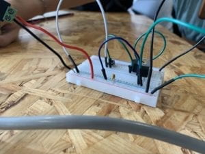
My partner and I had a hard time when we began making this circuit. In the beginning, we had no idea how a breadboard worked. After instruction from the professor, we knew how current flowed through the different parts of the board. After this it was a matter of putting things and the board so they looked like the diagram. We had little struggle while building the rest of the circuit. One tip that I learned, was that we could just put the two ends of the capacitor next to each other, one in the input and one in the ground. This eliminated the use of a wire, which made the circuit less cluttered.
Circuit 2: Lamp
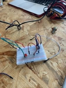
Building this circuit went significantly faster than the first one. It was basically the same process as the first, only with the addition of a resistor. The only issue that we came across was that we could not remember which end of the LED was the input and which was the output.
Soldering (Break In-between Circuit 2 and 3)
Our goal was to solder wires to an arcade button, so we could use it in our circuit. I had never done anything similar to this before, and I was slightly intimidated. Soon after starting, I realized that soldering is rather simple. If you’re not trying to make it look nice, that is. I found it difficult to place the melted solder where I wanted it to be. We were given the tip to wrap the wire through the hole in the arcade button, and this made it much easier to secure the wire to the button. 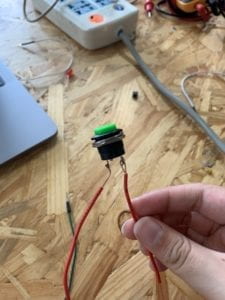
Circuit 3: Dimmable Lamp

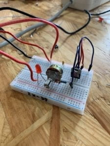 We had no major issues while building this circuit. The only that we came across was that, as we added more wires, we began to get mixed up which wire was going where. Next time, color coordinating the wires will help solve this.
Reflection
Overall, this recitation went smoothly. After the initial confusion with how the breadboard worked, there were basically no issues. I was excited to explore the different aspects of circuits in a deeper way than I had in the past. The versatile nature of a breadboard can be used can help this experimentation.
Reading questions
Question 1
The article highlights, that in order for something to be interactive, both parties must “listen, think, and speak.” This is not something that a circuit can do. For example, Circuit 1’s buzzer only made sound as a reaction to human input. Closing a switch to allow current to flow through the circuit is not the circuit listening, thinking, and speaking. Therefore it is not interacting, it is simply just reacting.
Question 2
Interactive design and physical computing are the two essential components that make up interactive art. Without these, interactive art cannot be made. Interactive design explores how beings can interact with the said design. For example, Zach Lieberman’s design for the drawing device cannot draw without a human using its sensors. Physical computing is when the hardware and software in a computer are able to sense to the input put in by humans.