Date of Recitation: March 16, 2019
Documented On: March 17, 2019
Partner: Arthur Gu
Reflection:
The objective of Recitation #4 was to create a working drawing machine with the help of an H-bridge to assemble the circuit. I finished the first two exercises by myself and proceeded to join Arthur for the third and final step of the recitation. Despite being informed of the possible damages that may occur during the exercise, I made the final decision to work on my own laptop for easy accessibility and time efficiency. This time around, I felt much more confident in my understanding of the Arduino process and its mechanics, but nonetheless, I still required assistance at certain points of the exercise.
Step 1: Build The Circuit
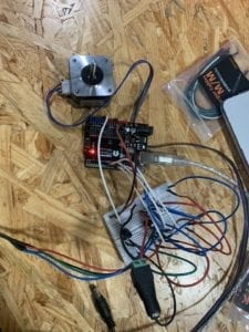
The first step was the most straightforward one out of the entire exercise. I placed the provided H-bridge onto the breadboard, ensuring that the bridge’s half circle icon faced the top of the board. While doing so, I also made sure to position the component in the middle of the breadboard knowing that each pin needed to be connected to separate parts of the Arduino board and stepper motor. Following the h-bridge, I simply followed the recitations reference in order to understand its schematics. Noting the large number of jumper cables being used, I made sure to keep the breadboard as clean as possible by using red and black to indicate power and ground respectively. (Mistake: Black should be used to indicate ground). In regards to other components, I tried my best to use a uniform color amongst them. I first connected the Arduino’s 5V to the breadboard power column and the Arduino’s GND to board’s ground column, a method I use to keep the breadboard clean as well as for easy access to either component. I follow the reference and attach each component carefully, ensuring that no mistake is made so that I could refrain from both, burning the Arduino and damaging my laptop. I interconnect the Arduino with the breadboard and H-bridge, all while leave space for the stepper motor’s pins. I then use 4 separate cables (red, blue, green and black) to attach the motor to the circuit, placing them in slots: 3, 6, 11 and 14 of the H-bridge. I then upload the pre-installed stepper_oneRevolution code to the Arduino, then proceeded to eject the component from my laptop and reattach it to the communal USB port provided during the recitation. It was a relief to see that motor began to turn upon the circuit’s attachment to its external power source.
Step 2: Control Rotation With A Potentiometer
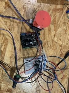
The second step was a bit tricky. I went into the exercise with fear of failure and the possibility of messing up the circuit as a whole. I attached the potentiometer in the extra space below the H-bridge spreading the pins across the middle of the breadboard. I was aware that the potentiometer needed to be connected to power, ground and an analog pin, but was not sure which pin was to be attached to which. I went to my laptop and began to look through lectures slides and previous recitations, hoping to garner more information about the potentiometer. I was not unable to find my answer and so resorted to searching the internet for an answer to my confusion. When Google also failed to provide me with a solution, I decided to ask for help from one of the teaching assistants. I informed her of my confusion and she showed me while pointing to the potentiometer which pin was which. I learned that the single pin on one side needed to be connected to analog, whereas the remaining two needed to be connected to both power and ground, on this side, the order did not matter. I quickly connected the potentiometer with the Arduino’s A0 slot with a white cord and continued to attach the remaining pins to the power and ground columns of the breadboard. After I implemented the potentiometer into the circuit, I went straight to work on the code. I opened the MotorKnob example code and copy and pasted it into my original code. Then, following the instructions, I switched the steps amount from 100 to 200, implemented the A0 code and attempted at working with the map() function. I was still confused about map() and so asked for help once again but from a different teaching assistant. The assistant took one look at my code and knew what the problem was. She told me that I did not need to combine the MotorKnob and OneRevolution codes for Step 2, and in fact, only required MotorKnob for the circuit to work. I followed her words and quickly reopened the example code and worked from there instead. She instructed me on how to use the map() function, and with her help, I was immediately able to get the circuit working with the turn of my potentiometer.
Step 3: Build A Drawing Machine
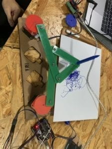
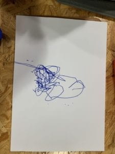
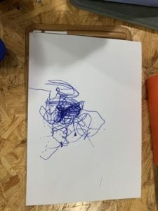
For the third and final step, I mentioned that I worked with my previous partner, Arthur, to create a cooperative drawing machine. We gathered the necessary material required and began to assemble them on top of our respective stepper motors. The mechanical arms were a bit difficult to assemble due to the clothespins’ lack of reliability. They would often fall out of their position, causing the entirety of the drawing machine to fall apart. After assembling the machine, we expected everything left remaining to be a walk in the park. This was, unfortunately, not the case. I placed the pen into position and realized that the pen did not come close to reaching the table and the paper. We could not lower the mechanicals arms in fear of them breaking all over again, and so looked for different solutions to help our situation. Arthur suggested that we level the paper upwards so that the pen would be able to reach it and draw upon it. The things surrounding us were either too tall or short in terms of height, we needed the perfect item to level the paper above the table. This is when Arthur remembered he had brought his iPad to class. He eagerly took it out of his bag placed it underneath the drawing paper. The iPad worked perfectly for our situation. Afterward, we turned on both our motors and continued to play with our potentiometers to maneuver the pen in certain directions. Soon, the motors began to emit abnormal sounds, a result that terrified both my partner and I. We realized that there was nothing we could do about the scratching and screeching, as it was due to the friction between the motor and the 3d printed motor couplings that laid upon them. Not wanting to prolong the sound effects, we tried our best to draw something on the paper. The miniature nature of the potentiometers coupled with the restrictions of the motor and its directions made it extremely difficult to attempt at creating an actual design. Due to time restrictions, we were unable to create an art piece that met either of our expectations. Nonetheless, the activity was very enjoyable and was probably one of my favorite recitations to date.
Questions and Answers:
Q1: What kind of machines would you be interested in building? Add a reflection about the use of actuators, the digital manipulation of art, and the creative process to your blog post.
A1: If I am to be completely honest, I have always complained about my abundant stock of long dry hair and the difficulty behind washing it, drying it and then styling it. While my short-haired friends are ready within the half hour, I have to plan ahead in order to compensate for my hour-long process. To help my fellow long-haired individuals, I would love to create, possibly in the future, an inexpensive automatic hair-washing machine. I would lie down on the machine, and wait as the sensors of the machine detect the presence of my hair and begin its work of shampooing, conditioning and possibly a head massage. I would aim for the entire process to be completed within 10-15 minutes. Once the process is finished, I will continue to dry my hair as usual and ultimately, have my hair process be cut down by 30-40 minutes. The end results would be similar to that of a salon-worthy blowout. After this first machine, I could possibly even go on to creating an automatic hair-drying machine that functions to dry my hair within seconds. This will be difficult to achieve, but would be something I’d be heavily interested in producing. Actuators, as I have learned are devices that have the sole purpose of developing a certain force and or motion that allows machines and other devices to function properly. In this recitation, the actuator being used is that of a linear actuator, the stepper motor. The motor provided the circuit with a source of rotary power, allowing me to create a fully functioning drawing machine. The art we created through this recitation originated with the digital manipulation of actuators. Arthur and I manipulated our own potentiometers and tried out best create some sort of design with our digital creation. We went into the design quite blindly, wanting to first get a hang of the controls and process before figuring out a real design and the creative process behind it. However, due to amateurism, a lack of time and the instability of the machine, Arthur and I were unable to truly create a design that we wanted, making the creative process both shallow and short. The final result was nothing but a collection of scribbles at the center of the paper, resembling that of extreme abstract art. Possibly, with more understanding of the controls and a better base, Arthur and I could reconstruct the machine at a later time, and form another attempt at producing a creative design.
Q2: Choose an art installation mentioned in the reading: “ART + Science NOW, Stephen Wilson.” Post your thoughts about it and make a comparison with the work you did during this recitation. How do you think that the artist selected those specific actuators for his project?
A2: The art installation I have chosen to reflect upon within “ART + Science NOW, Stephen Wilson (Kinetics Chapter)” is none other than Daniel Rozin’s Mechanical Mirrors: Wooden Mirror (1999-2018). Ever since I’ve learned of the definition of interaction within this course, I was always highly interested in mirrors and art installations that translated movement and or the present onto a physical platform through digital means, and not just through photography. Rozin’s installation is a perfect example for one of these interactive “photographic” moments. His project compared with the exercise I completed for recitation 4 is vaguely similar in essence. Both of them are inspired by the objective to draw and illustrate, however, while our project revolves around design, Rozin’s installation is focused on displaying reality through different material, in this case, wooden blocks. With Mechanical Mirrors, Rozin electromechanically manipulates the wooden blocks to seamlessly recreate reality. He creates a system that reads through its camera lenses, the movement of light and the transitions in grey scale values. With these values, the installation “adjusts the blocks accordingly” with hundreds of actuators. The servo motors used, ultimately grant Rozin with the manipulation and flexibility he needs. To be specific, Rozin used a total of 830 servo motors to accompany the 830 wooden blocks for this specific art installation.