Date Of Recitation: February 22, 2019
Documented on: February 25, 2019
Partner: Citlaly Weed
Reflection: Recitation 2 focuses on familiarizing oneself with the Arduino software and hardware through a total of 4 attempts at different circuits. For all circuits, I worked with my partner, Citlaly, who I had a great time creating circuits with. For continuity and time-efficient reasons, we decided that we would use Citlaly’s laptop for all coding and Arduino exercises. Since the both of us had already acquired an amount of knowledge from the first recitation and listened closely during the week’s lectures, the diagrams for circuits 1, 2 and 3 were all quite straightforward. We completed all 3 required circuits, and made significant attempts at circuit number 4 but was ultimately unable to complete it due to time constraints. Citlaly and I had chosen not to replace the switches with arcade buttons from the first recitation in order to leave more time for circuit 4, which was proven to be quite difficult.
Circuit 1: Fade
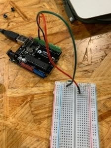
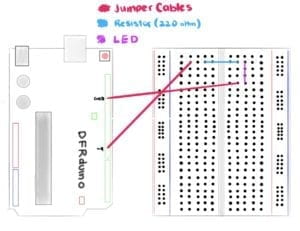
The purpose of the first circuit was to have a LED fade both in and out with the Arduino software and physical board. Citlaly and I grabbed two jumper cables, a 220-ohm resistor, and a LED to accompany the Arduino board and breadboard. We followed the clear diagram provided on the recitation website and got straight to work. The first step was to place the 220 ohm resistor onto the breadboard and into row 2 of columns D and G, knowing that the breadboard’s connection is divided into left and right. We then used a green jumper cable to connect one end of the resistor to the power on the Arduino board. Afterward, it was time to plant the LED. We made sure that the anode connected with the resistor and ultimately to the power supply by placing it in row 2 of the breadboard. Lastly, Citlaly and I attached the cathode end of the LED to a red jumper cable in row 5, which we would then connect to the Arduino board’s ground. We connected the circuit to Citlaly’s laptop through the Arduino board and continued to follow the instructions provided. We opened the Arduino software, went to file and found the Fading example under 0.3 Analog. Citlaly uploaded the code, but we were met with our first failed attempt. The LED did not light up, nor fade in and out as it was supposed to perform. This is when I remembered a tip our professor, Mr. Young had informed us about in class. I went to tools and looked down to find the Board and Port categories, and selected the appropriate port for the Arduino software. After completing the selection, we tried to upload the code once again, and to our surprise, the circuit worked this time around.
Circuit 2: toneMelody
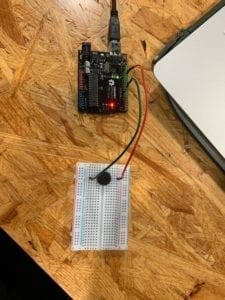
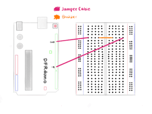
The output that Citlaly and I strived to achieve for circuit 2 was for a speaker to emit a specific melody produced within Arduino. We made sure to disconnect the circuit from the laptop and remove both the resistor and LED from the breadboard as they were no longer needed. Citlaly and I placed a speaker or buzzer near the middle of the breadboard, ensuring that its pins were connected to separate sides of the circuit board. Following this, we connected the red and green jumper cables to each side of the buzzer and connected the Arduino board with the laptop once again. Citlaly and I were confident that we hadn’t made any mistakes and continued to open a new Arduino page with the toneMelody example found under 0.2 Digital. Unfortunately, we were unable to have the circuit working on our first attempt. Since we were confused as to what went wrong during the seemingly simple circuit, we asked for help from the teachers and assistants present during recitation. We soon learned that we had misplaced the red and green jumper cables that connected to both ground and power on the Arduino board to the incorrect sides of the buzzer. Our initial belief was that the position in which the components were connected did not matter, as long as they were attached, the circuit would work. This was ultimately, incorrect. We turned the buzzer around so that the anode side would connect to green power cable, while the anode would attach to the red ground cable. With our second attempt, we were able to successfully make the buzzer release a small melody, essentially completing the second circuit.
Circuit 3: Speed Game
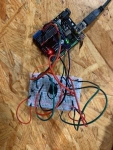
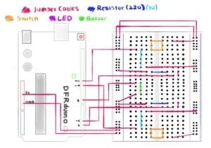
The third circuit was by far the most interesting circuit as well as the most difficult one to follow in terms of its foundation for it implemented a sense of interactivity for both Citlaly and I. We placed all major components down such as the buzzer, the switches, the LEDs, and the resistors in their positions on the breadboard and continued to interconnect all the pieces with an assortment of jumper cables that ranged from short to long and long to short. With the jumper cables, we also connected the breadboard to the Arduino base by utilizing slots, D11, D10, D8, D3, D2 as well as GND and 5V. When it reached this part of the circuit, things began to grow confusing as the number of components on the breadboard increased with each step. The circuit, unfortunately, did not prove to be a success as the LEDs failed to show any response to the manipulation of either switch. We then decided to utilize the multimeter to test the resistors, as we were aware that any single mistake would be crucial to the circuit. The multimeter discovered that one of the resistors presumed to be of 220 ohm was in fact a 10k ohm resistor. We immediately, switched the 10K ohm resistor with a new 220 ohm one and replaced it on the breadboard. We did a double take of the entire breadboard and made another attempt to get the speed game working. With the port and board categories accurately chosen, the Arduino board connected to the laptop and all components seemingly fitted into their rightful positions, we uploaded the Arduino code once again. Both of us then pressed the switches repeatedly and vigorously in an attempt to have our LED turn on first, which ultimately resulted in Citlaly’s victory. Circuit 3 was confusing at first, but after we traced our steps and focused our attention on each and every component, we were able to spot the mistake almost immediately, which allowed us to complete the third exercise with ease.
Circuit 4: Four-Player Speed Game
For this optional circuit, Citlaly and I partnered up with two other classmates from our recitation. We began to discuss the solutions that could help us transition our two-player game into that of a four-player one. We decided to list down the number of our switches, and the colour of the jumper cable that would connect to each slot in the Arduino board and breadboard. We noted the number of the slots we used as well in order to implement them into our code in the future. We soon hit a rough patch while trying to interconnect both breadboards with a single Arduino base. Unfortunately, due to time constraints, our group was unable to complete the fourth circuit despite our great efforts and attitude.
Questions and Answers:
Question 1: Reflect how you use technology in your daily life and on the circuits you just built. Use the text Physical Computing and your own observations to define interaction.
Answer 1: Technology is found everywhere and is now inevitable when it comes to performing certain tasks on a daily basis. I use the microwave for breakfast, my laptop to complete assignments, and my smartphone to read the latest news. Technology has changed the way individuals communicate, play, work, study, learn and behave around one another. With its ever growing area for improvement and creation, technology is most of the times, created to improve all lifestyles. When this technology is partnered with physical computing, the possibilities are endless. As stated in the “Introduction to Physical Computing”, the very definition of physical computing entails the “creation of a conversation between the physical world and the virtual world of the computer”, which ultimately creates an interaction between the two worlds. According to the reading, two subjects require input, output and processing for an ‘interaction’ to occur between them,. They react with one another through a cause and effect complex that allows an output to be produced at the conclusion of the interaction. The circuits created in recitation 2 are perfect examples of physical technology combined with the wonders of physical computing. The correct wiring of components of the breadboard and the proper coding upon the Arduino software allows the circuits to produce results (output) such as: playing music, turning on/off lights as well as creating games (for leisure). The interaction between the physical world and its counterpart, the virtual world create technology designed for all audiences, and will continue to create for years to come.
Question 2: If you have 100,00 LEDs of any brightness and colour at your disposal, what would you make and where would you put it?
Answer 2: If I were given 100,00 LEDs of any brightness and any colour at my disposal, I would perhaps, If I had the knowledge and capability to do so, create an art piece that would have all 100,000 LEDs positioned so close together that from a distance they would appear to create a flat surface of lights. I would then create a program that allows the user to draw a simple image, or write a note that would eventually project onto the 100,000 LEDs as if it were being projected onto a TV or a screen. Each LED would change into a colour in respects to the design and or message the user has created on the program. Ultimately, it would enlarge the design and bring the piece to life by allowing it to shine through the lights of 100,000 LEDs. This idea would of course, require a lot of knowledge in regards to both computer programming and light engineering, but would ultimately be an amazing project if it were to be created in real life.