Date: February 15, 2019
Documented on: February 20, 2019
Documented By: Celine Yu
Partner: Arthur Gu
Aim: To create simple circuits and to familiarize with its schematics.
All Materials (One of Each):
12 Volt Power Supply: The power supply provides a measurement of 12 Voltage for all 3 circuits of the exercise, allowing the circuit to function properly.
Breadboard: The piece of equipment is used to create prototypes of circuits, and to experiment with the circuit design. It is the board where other circuit components connect to one another.
Push-Button Switch / Arcade Button: Both the Push-Button provided in class, and the Arcade Button made during the separate soldering exercise act as the “input” mechanism for all 3 circuits. When either button is pushed, the circuit will, depending on its modifications either turn on the speaker or turn on and dim a LED.
LM 7085 Voltage Regulator: The Voltage Regulator is strictly in charge of ensuring that the amount of power output does not exceed harmful levels. It regulates the voltage to maintain it a proper level that has sufficient power to complete the circuit’s purpose or course of action.
Capacitor (100 nF ): The capacitor is simply used to store energy for the circuit, it then provides the circuit with sufficient energy where and when it is needed.
Barrel Jack: The barrel jack is an electric power connector that attaches to both the breadboard and the power supply, connecting the circuit to its power source when it is required.
SEVERAL Jumper Cables: The jumper wires, otherwise known as electric wires are attached to the breadboard to interconnect all other components with one another, allowing for the circuit to work.
Buzzer: The buzzer acts as the component that displays the final output of the first experimental circuit. When wired correctly, the buzzer will sound off with a high pitched noise to indicate that the circuit has been completed successfully.
Multimeter: The multimeter is a device that is designed to measure values of electric current, voltage and resistance. In this experiment, the multimeter is used to identify any 220-ohm resistors that can be used for both circuit 2 and circuit 3.
Resistor (220-ohm): The resistor is used in the circuit to regulate and reduce current flow. In both circuit 2 and 3, the resistor is responsible for limiting and regulating the current flow, ensuring that there is no possibility for too much current to flow through the LED and burn it.
LED: The LED or light emitting diodes come from the diode family and acts as the light source as well as output for both circuit 2 and 3.
Variable Resistor: The potentiometer (Variable Resistor) is the additional component to circuit 3 that separates it from circuit 2. It is a voltage divider that measures the electric potential of a circuit. Within circuit 3, the potentiometer is connected on the breadboard to both the LED and the alternative resistor. Within this exercise, It provides the user with the ability to alter the brightness of the LED
The Process:
Beginning: For my first attempt at creating circuits, there were many challenges I had to overcome to complete the task for recitation. Following the completion of our heavily packed soldering session, my partner, Arthur and I familiarized ourselves with the circuits’ instructions. Our first step of business was to use the multimeter to determine if whether or not we had obtained the correct 220-ohm resistor. To complete this step, we took the red and black probes attached to the multimeter and used them to make contact with either end of the resistor, checking the screen of the multimeter for an indication of 220 ohms. After a few attempts, we finally found the perfect one and continued on with the exercise.
Circuit 1 Door Bell:

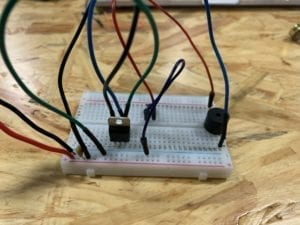
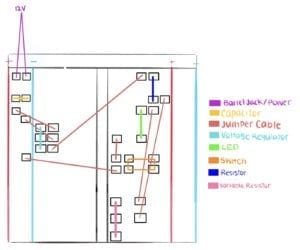
Given that this was our first time working with circuits, Arthur and I had no idea where to start when it came to creating them. This is where we decided to ask for assistance from one of the teachers at recitation. Our teaching assistant guided us through the diagrams, familiarizing us with its language and symbols. She taught us how to begin setting up the breadboard, reminding us of its directional wiring as well as the ground and power complex. Looking upon the diagram, it was evident that certain components were connected to the power (+) while others were attached to Ground (-). These were quite easy to place due to the color coding of the breadboard that indicated the power column with a red (+) and the ground column with a blue (-). Following the placement of the yellow capacitor, the barrel jack, switch, and the power supply in their rightful places, we moved onto the voltage regulator. We attached the component to the breadboard in a vertical fashion, an orientation that would allow the three protruding pins on the bottom to attach in 3 different rows for the input, ground, and output. The only component left standing was the buzzer, the immediate output of the circuit. We discovered from the diagram how the speaker was to be connected to both the switch and the voltage regulator with separate jumper cables. To ensure that the buzzer would be attached to separate connecting rows of the breadboard, we attached it in a horizontal orientation that ultimately crossed the dividing gap in the middle of the breadboard. Both Arthur and I remembered that due to the separating line in between, the rows on either side of the division were not connected underneath. While placing the major components down in the breadboard, we also made sure to connect them using the jumper cables in order to refrain from confusing ourselves in the end. Nonetheless, Arthur and I successfully completed the first circuit, allowing the buzzer to emit a high pitched sound upon the switch being triggered by a press.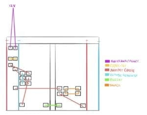
Circuit 2 Lamp:

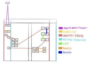
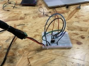
The first decision we made was to take out the buzzer that no longer had any use for the circuit. We used the jumper cables to then wire the resistor to both the voltage regulator and the LED, which was also attached during the process. The diagrams provided assisted us in the project by a large margin. We relied on the visuals and descriptions to play a game of mix and match to identify the components we had never used nor seen prior to the exercise. Other than the addition of the resistor and LED to the breadboard, we kept everything else the same, making sure that we wouldn’t disrupt the circuit. It was a relief to see that our second attempt at creating a circuit went just as successful as the first, as we watched the LED enlighten with a press of the button (switch).
Circuit 3 Dimmable Lamp:

The third circuit was the most difficult of the three and one of the only exercises Arthur and I struggled to complete within the try. Despite the minor difference between circuit 2 and 3, the two of us grew confused by the number of components on top of the breadboard. We replaced the LED and resistor to make room for the largely scaled variable resistor that would dim the brightness of the LED when the circuit was completed. Thanks to the pictures in the instructions, my partner and I learned that the variable resistor needed to be connected to both the LED and the other resistor by their respective outlets, and not randomly. We made our first attempt at the circuit, but to our dismay, it was neither able to dim the light of the LED but also turn on the LED. This is where Arthur and I examined the breadboard closely and decided to move around a few components in an attempt to make the board neater. As I altered the breadboard, Arthur watched over for any mistakes that could possibly occur and vice versa. We realized that the source of the problem was the misplacement of a single jumper cable, swiftly, we repositioned it into the correct space. To our expectations, the circuit ended up working perfectly, a great relief to both Arthur and I as we played around with the variable resistor. The fourth and last circuit of recitation included a minor switch between the push button switch and the arcade button. This switch of the two buttons indicated a change in the input and interactive component. Arthur and I made sure to follow the tips and reminders we gave ourselves, and by keeping neat and focused on the circuit, we were able to complete the final circuit quite easily.
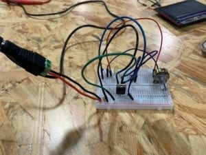
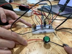
Conclusion: For the most part, the circuits worked perfectly fine for my partner and I. There were a limited amount of moments where the circuit did not work to our expectations, which as mentioned earlier, was during circuit 3. The light refused to turn on nor dim, a problem we fixed with patience and close observation of the wiring and modifications of our breadboard. We helped each other when we failed to comprehend certain portions of the exercise and made sure to look out for each other’s mistakes and praise our accomplishments. There was one particular mistake that both of us continued to make throughout the exercise. Both Arthur and I would forget to unplug the breadboard from its power source before modifying its components, a mistake that we were warned about many times during the instructions at the beginning of recitation. We were also very thankful that none of our materials burned out during the recitation, something that occurs often when the breadboard is wired incorrectly. We learned a lot of information from this recitation including how to read diagrams, the purpose and names of many circuit components as well as useful tips such as: keeping the breadboard neat and tidy as well as unplugging the circuit from its power source while modifying. Overall, the recitation was enjoyable and was the perfect introduction for me into the world of creating circuits and interaction lab as a whole.
Questions and Answers:
Q1: After reading “The Art of Interactive Design,” in what way do you think that the circuits you built today include interactivity? Please explain your answer.
A1: From the reading of “The Art of Interactive Design,” I learned that interaction is the “cyclic process in which two actors alternately listen, think and speak” (8). Understanding this, I personally believe that in regards to the circuits created during this recitation, there are two forms of interactivity present. The first interaction occurs between the users and the switches (buttons). Through these switches, the user is able to interact with the circuit to provide it with its input, which would ultimately through the process, cause for an output to occur. The second form of interactivity occurs between all the components of the circuit. Each component on and off of the breadboard have their individual responsibility for the overall circuit. As the input is triggered by the user, all components work together in a cause and effect fashion to complete the circuit and produce an output. This is why interactivity is included in the circuits, for all components react with one another to create a final product.
Q2: How can Interaction Design and Physical Computing be used to create Interactive Art? You can reference Zack Lieberman’s video or any other artist that you know?
A2: Art is a broad category that can be expressed through a variety of different means and methods, for there is no true answer to what exactly is art. Interactive art goes a step further from traditional art by implementing interaction into its user ability. This form of interactive art can be created by both interaction design and physical computing, as digitizing art brings an unlimited amount of possibilities to the question of interactive art. With physical computing, the artistic creator will be able to bring the art to life with lines of code (Zach Lieberman), a feat that is impossible to achieve with traditional art.
Resources:
Recitation: https://wp.nyu.edu/shanghai-ima-interaction-lab/recitation-1-electronics-soldering/
Art of Interactive Design: http://s3-ap-southeast-1.amazonaws.com/ima-wp/wp-content/uploads/sites/3/2017/08/05164121/The-Art-of-Interactive-Design-brief.pdf
Zack Lieberman: https://vimeo.com/9939042