Tasks:
- Build three circuits, which are Door Bell, Lamp, and Dimmable Lamp
- Solder long wires to an arcade button and replace the push button switch with the soldered arcade button.
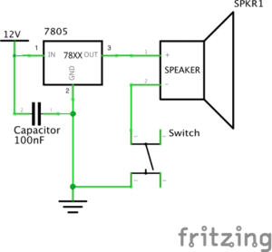
Circuit 1: Door Bell
Components:
- 1*Breadboard
- A base for holding and connecting the components
- 1*LM7805 Voltage regulator
- To maintain a constant voltage level. In this circuit, it is used for converting 12V into 5V.
- 1*100 nF Capacitor
- To store electrical energy in an electric field.
- 1*Switch
- Control the flow of circuit. When pressed, it connects the circuit; when released, it disconnects the circuit.
- 1*12volt power supply
- Power source which provide 12V power for this circuit.
- Jumper cables
- To connect the components in the circuit.
- 1*Barrel jack
- An electrical connector for supplying direct current (DC) power.
- 1*Buzzer
- Creates sound when the circuit is connected
Diagram:
Video:
Process:
Since this recitation was our very first class for interaction lab, my partner and I both had a very limited knowledge about building a circuit. At first, we thought the circuit would work as long as we follow the diagram, so we just kept arranging the components in different formats that ‘looked like’ the one in the diagram. However, the buzzer didn’t make any sound, so we decided to ask one of the assistants, Jingyi for help. Before we asked for help, we lacked lot of knowledge about how the breadboard work, which now I think was a very crucial problem, since all of the components need to be connected on the breadboard. Later on, Jingyi taught us how the holes on the breadboard are connected and which parts are supposed to be the ground and the power supply. Furthermore, she also told us that the legs of the switch are self-connected diagonally, so we need to be careful that we shouldn’t connect two legs from the same side. Eventually, we rebuilt the circuit, which worked successfully in the end.
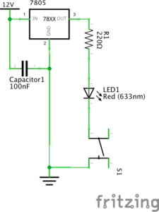
Circuit 2: Lamp
Components:
- 1*220ohm Resistor
- To create resistance in the flow of electric current
- 1*LED
- Emits light when the circuit is connected
- 1*Multimeter (missed)
- Used to measure resistance.
- 1*Breadboard
- A base for holding and connecting the components
- 1*LM7805 Voltage regulator
- To maintain a constant voltage level. In this circuit, it is used for converting 12V into 5V.
- 1*100 nF Capacitor
- To store electrical energy in an electric field.
- 1*Switch
- Control the flow of circuit. When pressed, it connects the circuit; when released, it disconnects the circuit.
- 1*12volt power supply
- Power source which provide 12V power for this circuit.
- Jumper cables
- To connect the components in the circuit.
- 1*Barrel jack
- An electrical connector for supplying direct current (DC) power.
Diagram:
Video:
Process:
After we built the first circuit, my partner and I had better understandings on the functions of the components. Since the assigned circuits were pretty similar to each other, we only changed the part that need to be changed. Therefore, we replaced the speaker with the LED and resistor, and keep the remained the other components in the same position. During building this circuit, we didn’t encounter any difficulty, and it worked successfully in our first attempt. However, there is one thing need to be mentioned. Because we were only focusing on the diagram, we forgot to connect the multimeter, which is not shown in the diagram. Thus, next time I will make sure that we didn’t miss any step before we move on to the next task.
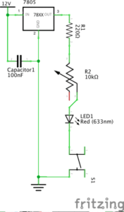
Circuit 3: Dimmable Lamp
Components:
- 1*10K ohm Variable Resistor (Potentiometer)
- To create resistance in the flow of electric current and being used for changing the brightness of the LED in this circuit.
- 1*Breadboard
- A base for holding and connecting the components
- 1*LM7805 Voltage regulator
- To maintain a constant voltage level. In this circuit, it is used for converting 12V into 5V.
- 1*100 nF Capacitor
- To store electrical energy in an electric field.
- 1*Switch
- Control the flow of circuit. When pressed, it connects the circuit; when released, it disconnects the circuit.
- 1*12volt power supply
- Power source which provide 12V power for this circuit.
- Jumper cables
- To connect the components in the circuit.
- 1*Barrel jack
- An electrical connector for supplying direct current (DC) power.
Diagram:
Video:
Process:
Since everything went smoothly when we were completing the second circuit, we use the same method to build the third circuit. We disconnect the LED and the resistor, and connect the variable resistor in between them. However, the circuit didn’t work because the lightness of the lamp didn’t change while we rotated the variable resistor. We thoroughly checked the connections between the components. Later on, we then found out that we connected the resistor and the variable resistor incorrectly. According to the picture, the resistor should be connected to the middle branch of variable resistor, but we connected it with the right branch instead. We fixed the mistake and right after that, the brightness of the lamp are able to changed as we rotated the variable resistor.
After we finished with building the last circuit, we both forgot the second task, which is switching the push button switch with the soldered arcade button. Therefore, this mistake again remind me that, for the next lab, I should double check everything before moving to the next step.
Although we didn’t do the task, but to replace the push button, I think we can just take the switch off and connect the jumper cables with the arcade button by setting them in the same row.
Reflection
At the beginning of the recitation, my partner and I had a hard time on trying to figure out how to connect the components. But after the assistant provided clear explanations of the functions of the components, we were able to build the circuits in a short time. Therefore, it is really important to be familiar with the components before doing the task. Also, as I mentioned, my partner and I both forgot to do some parts of the lab, so next time I should read the instructions more thoroughly and have a better time management, so that we won’t be skipping any step again.
Questions
After reading The Art of Interactive Design, in what way do you think that the circuits you built today include interactivity? Please explain your answer.
The circuits which we built in the recitation do include interactivity. When we pressed the button, the LED light and buzzer gave feedbacks by making signals. However, in “The Art of Interactive Design”, the author states, the case like light lighting up in a fridge is an example of a low level of interactivity. Therefore, although the circuits we built do include interactivity, I think it only include a really small extent of interactivity. Comparing all of the circuit,s the last circuit is the one with the highest level of interactivity, since we can control the level of brightness by rotating the variable resistor.
How can Interaction Design and Physical Computing be used to create Interactive Art? You can reference Zack Lieberman’s video or any other artist that you know.
Both interaction design and physical computing can be used as tools to create interactive art. For example, The EyeWriter in Zach Lieberman: Interactive Art, enable Tony, a graffiti writer who is paralyzed, to draw digital images with movement of his eyes. The Eyewriter allows Tony to be able to interact with his environment. Therefore, I think it is a great example that reveals how physical computing can create tools that allow humans to interact with the environment.