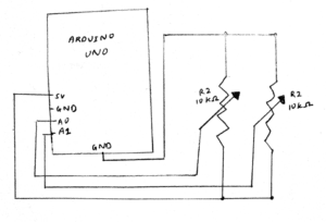
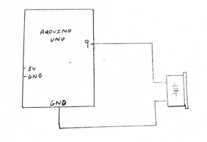
During last week’s recitation, we were required to use Serial Communication to send data from Arduino to Processing and vice versa. This was a lot of work and it took quite some time before I was able to correctly input the right code. I found myself getting confused as to when certain lines of code should be typed in Arduino and when they should be typed in Processing but overall it was a success!
Exercise 1:
For this exercise we were asked to use Arduino to send two analog values to Processing. I first built my circuits with two potentiometers and connected this to my Arduino board. I had to keep in mind which pins I was using (ie. A0 and A1). After I had built my circuit I opened up the example code given to us and looked at how I could edit it. I first opened the “multiple values from Arduino to Processing” on Arduino and made sure I had only two sensors and that they were defined in my local variables underneath void loop(). I then opened up Processing and made sure I had changed the number of values to 2 since I was using only two sensors. I also had to change my Serial.list number to [1] depending on the order of my ports, which our professor showed us how to do in class. I then began to draw my two ellipsis that I would control with my potentiometers on Processing. I set up the size under void setup() and began to draw the ellipse under void draw(). I got some help from the learning assistants and learnt that I could write this code as “ellipse(sensorValues[0], sensorValues[1],50,50)” as I had already defined my sensor variables earlier. This made it easier to work with. I also set the background to black so that I could see the circle moving. The potentiometers worked and moved the circle based on its x and y positions.

After I drew the circle, I was required to change this to a line and create a drawing similar to “etch a sketch”. I learnt that for this I would have to define new variables (previousX and previousY) so that my line would start drawing from its previous point each time I turned the potentiometer. Under void draw() I drew the line with the code: “line(previousX, previousY, sensorValues[0], sensorValues[1]).” I also had to make sure I equated the two “previous” variables to the appropriate “sensorValue” variables. This was quite interactive as I was designing my own etch a sketch on Processing using two potentiometers through Arduino.

Exercise 2:
For the second exercise we were required to make a processing sketch that sends values to my Arduino based on my mouse’s x and y position. I had to make sure the Arduino code could read the serial values from Processing and translate this into music which would be heard through the buzzer. I had to use the tone() function to this exercise. I copied over the pitches.h file from tone() and inserted it into a new tab within my “multiple values from Processing to Arduino” code on Arduino. I then went to the main code and typed in #include “pitches.h” to let Arduino know I wanted my melody taken from that file. I also copied over the notes I wanted to be played. Next, I made a circuit and made sure my buzzer was connected to digital pin 9 on my Arduino. I then included this under void setup(). Under void loop() I only used the example code provided for “tone”. I had to modify which sensorValues I was using. I then went to Processing and edited the code so it had 2 sensors and the appropriate Serial.list number. I then included an if function under void draw() which stated that if (mousePressed) values[0] = 1; else values[0] = 0.I also defined Values [1] = mouseX. This allowed me to change the sound emitted from the buzzer depending on where my mouse was placed on the x-axis in processing. I did the same for mouseY. This was interactive as I had to click on Processing using my mouse in order for sound to play from my buzzer through Arduino.
