In our second recitation we were required to build three separate circuits using our Arduino Board. I worked with Tian Tian in building the circuits and we were successful with building all three even though we came across a few obstacles along the way.
Circuit 1: Fade
For the first circuit we were required to use the Fade example on Arduino. The Fade example uses analog output (PWM) to fade an LED. I later learnt that PWM which stands for Pulse Width Modulation is a way to obtain analog results using digital means. By using PWM, the digital pin turns on and off very quickly depending on the ratio thereby creating a fading effect. To begin, we had to connect our LED to our breadboard with a 220 ohm resistor and ensure that the anode was connected to digital output pin 9 and the cathode connected to ground. We then uploaded the code for the Fade example found under the Arduino site. We experimented with the code by changing the values for the delay function and the fadeAmount.

Circuit 2 : toneMelody
For circuit 2, we were asked to use the toneMelody example using the piezo buzzer to play a little melody. We connected our speaker to the Arduino Uno but first had a few problems connecting the jumper wires properly as we kept inserting it to the sides of the buzzer instead of right in front of it (horizontally) as seen below to the left. We later learnt that this would not allow electricity to flow in order to activate the buzzer and changed the jumper wires to the correct position as seen below to the right.


We then uploaded the toneMelody code found in Arduino. The new thing we learnt here was that this specific code would require an extra file to be used which was the pitches.h file which would differentiate between the various music notes. We inserted this file by clicking on new tab and pasting in the pitches.h code found in the example under the Arduino website. The buzzer worked and played the melody we had uploaded!
Circuit 3: Speed Game
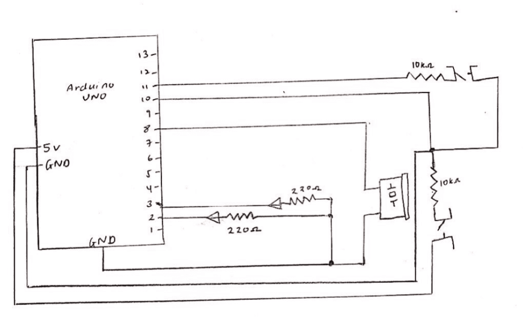
The third circuit we built was by far the most fun! We used the tinkercad site to make the Race the Led game. We had to connect two LEDs with the 220 ohm resistors as well as the piezo buzzer and two push buttons with the 10k resistor for each player. We copied the code from the tinkercad site and clicked on the serial monitor to begin the game. However, we had placed the jumper wires into the wrong digital output pins and so our game did not work at first. We then realized our mistake and upon placing them into the correct digital output pins the game began to work! We took pictures of when both players won, with the yellow LED turning on when Player 1 won and the red LED turning on when Player 2 won. Unfortunately, we had no time to pair up and make the fourth circuit.


 Schematic for Circuit 3
Question 1:
Looking at the circuits we had built I was able to realize how technology is used in our everyday lives through simple tasks such as turning on a light to ringing the doorbell at a friend’s home. In the reading on physical computing we see the role computers play in our day to day lives. Physical computing projects can be broken down into three stages, these being the input, processing and output. Interaction can therefore be defined as transforming an input through a certain process into an output. Sensors which are input transducers (ie. switches, resistors) would convert heat, light, motion etc. into electrical energy and output transducers such as motors and buzzers convert this electrical energy into forms of energy that the body can sense or see. I would say that this conversion of electrical energy to forms of energy that we can sense is a form of interaction as well.
Question 2:
We used the 10K resistor with the push button because if it is not used the voltage on the pin would “float” meaning it would show inaccurate results. Upon further research, I was able to understand that floating meant the Arduino pin is neither grounded nor receiving a voltage from an external source making the value inaccurate and therefore unreliable. The resistor is used also in order to prevent the circuit from short circuiting or blowing up.
Question 3:
If I had 100,000 LEDs of any brightness and color I would use it to build better road signals to alert drivers at night. Back home in Sri Lanka there were a number of accidents on roads built close to mountains/slopes as rocks would fall onto the cars following a rainstorm. By using these LEDs I would be able to alert drivers when rocks are falling faster than usual by increasing the pace at which perhaps red LEDs blink on and off, warning them to not drive further ahead.