For this week’s recitation, the basics of Processing were explored through the creation of a designed based on another artists’ previous artwork, for which I had the initial idea of creating a piece very abstract in colors and shapes.
The image I selected is called AII (Construction AII), and was created by, László Moholy-Nagy in 1924, with the intention of creating an architectural design in space, seemingly as if it were constructed by a mathematical formula. I chose this artwork with the purpose of expanding the concept of intersectional shapes, into a rather 3D plane, by utilizing the same shapes, but with a lot more variations and overlapping of different opacities in order to create a shadow-like effect within the artwork. Nevertheless, the idea in my thoughts was easier than when I actually initiated inputting it in Processing, as the code was very challenging for me at first.
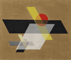
Original Image
The mayor challenge for me was locating myself and the drawing within the coordinates and scale of the graph. As I did not use simple shapes such as “rect” and in fact decided to draw “quad” due to the nature of the original image, I had difficulties identifying which corner corresponded to which coordinate. In fact, it took me nearly half of the recitation time to draw with the correct coordinates the center black polygon. Nevertheless, once I was able to place objects within the frame I had, the rest of the items were much easier to create. Colors and opacity on the other hand, wasn’t as complicated as I imagined before, except for the aspect of having to find the correct tone of brown for the background. After various attempts with the (RGB) color distinction, I just decided to use the color selector tool within processing for the efficiency.
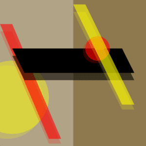
My Drawing
My final creation aligned with the original artists’ motif, as I also developed it around the idea of mathematical accuracy within the sizes of the geometric shapes in order to assemble the architectural-style piece. However, it differentiated with it, in the way that my creation attempted to encompass a deeper view into not only 2-Dimensional measurements, but also 3-Dimensional depth within the figures through shadows. Considering the nature of my idea, I consider that processing was indeed the best way to achieve my goal, as the input of x,y-coordinates allowed my measurements to be more precise, and the geometric figures to resemble an architectural stance.
Code: https://gist.github.com/arianaalvarezv/e8b72942ca2b25e4ca7886eacee6cf29
size(600,600);
background(#8E794F);

//whiteRectangle
beginShape();
fill(255,80);
noStroke();
quad(0,0, 300,0, 300,600, 0,600);
//quad(200,0, 400,0, 400,600, 200,600);
endShape();

//yellowEllipse
beginShape();
fill(255,255,0, 100);
noStroke();
ellipse(50,400, 300,300);
endShape();

//lightyellowEllipse
beginShape();
fill(255,255,0, 50);
noStroke();
ellipse(30,420, 300,300);
endShape();

//redRectangle
beginShape();
fill(255,0,0, 150);
noStroke();
quad(0,100, 50,100, 250,570, 200,570);
endShape();

//lightredRectangle
beginShape();
fill(255,0,0, 50);
noStroke();
quad(0,130, 50,130, 250,590, 200,590);
endShape();

//lightblackRectangle
beginShape();
fill(0, 150);
quad(50,230, 500,230, 550,330, 100,330);
endShape();

//darkblackRectangle
beginShape();
fill(0);
quad(50,200, 500,200, 550,300, 100,300);
endShape();

//redEllipse
beginShape();
noStroke();
fill(255,0,0, 150);
ellipse(400,200, 100,100);
endShape();

//redEllipse
beginShape();
noStroke();
fill(255,0,0, 50);
ellipse(390,210, 100,100);
endShape();

//lightyellowRectangle
beginShape();
fill(255,255,0, 50);
noStroke();
quad(300,50, 350,50, 550,450, 500,450);
endShape();

//yellowRectangle
beginShape();
fill(255,255,0, 150);
noStroke();
quad(300,20, 350,20, 550,430, 500,430);
endShape();