Recitation 1: Electronics & Soldering
February 15th, 2019
Objectives:
- Learn the basics of circuits by building three circuits
- Learn how to solder
Materials:
- 1 * Breadboard : a solderless device for circuit design
- 1 * LM7805 Voltage Regulator: converts to 5v and maintain the voltage level to be used by the buzzer
- 1 * Buzzer: creates a sound when connected to power
- 1 * Push-Button Switch: turns on and off to control electricity flow
- 1 * Arcade Button: same function as the switch (we solder a button in this lab)
- 1 * 220 ohm Resistor: an electronic component that adjusts the resistance of electricity and controls the flow of current to be used for the LED light
- 1 * LED: a type of diode as a light source
- 1 * 100 nF (0.1uF) Capacitor: an electronic component that stores electrical energy when the circuit is connected to power
- 1 * 10K ohm Variable Resistor (Potentiometer): adjusts the level of resistance to allow more or less voltage through
- 1 * 12 volt power supply: supplies power for the circuit
- 1 * Barrel Jack: connect power
- 1 * Multimeter: used to measure electrical properties like voltage, current and resistance
- Several Jumper Cables (Hook-up Wires): connects components of a circuit together
Exercise:
Partner: Robin Luo
Solder an Arcard Button
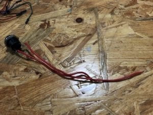
At the station, we soldered wires onto an arcade button using Tin. It was a challenging process melting the Tin and putting it at the right place. When we used the button in our circuits later on, we realized that it is better to use two different colored wires to distinguish input and output. We also encountered a problem with the button which will be discussed in detail in circuit 2.
Circuit 1: Door Bell
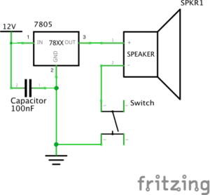
circuit 1 schematics
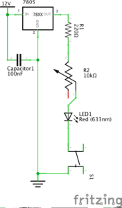
My partner and I did a lot of trial and error for the first circuit. We were confused about general practices like how the breadboard works, where to put the capacitor, the orientation of the voltage regulator. The first time we assemble the circuit, the buzzer did not ring. After talking to some fellows and “debugging the circuit”, we noticed two problems 1) the capacitor was misplaced and we had extra wires connecting to and from it 2) we got the orientation of the voltage regulator wrong. To fix these problems, we placed the capacitor next to the power supply from power to ground and got rid of any extra wires. We also rotated the voltage regulator.
The working circuit:
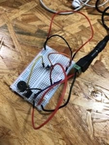
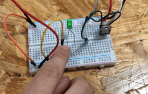
Circuit 2: Lamp
With experience from building the first circuit, we were more time efficient with the second one. Because we are given two resistors with different Ohms, we used the multimeter to find out the 220 Ohm one. Then we connected the resistor to the led and the circuit worked without a problem.
The working circuit:
Area for improvement: the wires for this circuit are quite messy, it would be better to rearrange and clean up them.
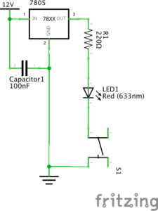
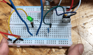
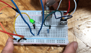
Circuit 3: Dimmable Lamp
We also did not have much trouble with assembling the third circuit. It was very similar to the second one except with the addition of a variable resistor to control the level of resistance and thus LED brightness.
Working circuit:
Switch the switches
For each of the circuits, we tried with both push-down button and the arcade button. We had an issue with the arcade button we soldered ourselves. The circuit would only work for the push-down button but not the arcade one. After consulting with a fellow, we used the multimeter to test if the button is working. It turns out that we might have accidentally bent the wire too much while soldering and that cuts down the current flow. When given a new working arcade button, our circuit worked again.
Questions:
Question 1:
After reading The Art of Interactive Design, in what way do you think that the circuits you built today include interactivity? Please explain your answer.
Interactivity can be a subjective term and should be treated on a relative, continuous scale instead of as a boolean value. The process of building the circuits was quite interactive to me as I got to experiment, make mistakes and eventually assembled them successfully. However, as circuits with only a button and an additional variable resistor for circuit 3, the pure degree of interactivity is quite low. Even though we were able to hear sound or see light, the interactivity of these circuits is comparable to that of the fridge example discussed in the chapter.
Question 2:
How can Interaction Design and Physical Computing be used to create Interactive Art? You can reference Zack Lieberman’s video or any other artist that you know .
Physical computing provides the software and hardware required to build interactive systems. And interaction design allows these systems to be created, altered and fitted for expressing specific ideas and evoking desirable behaviors and actions. Together they enable the creation of interactive art from the technical and artistical aspects as well as the sensory experience. The example mentioned by Zack Lieberman on eye tracking system for drawing is a perfect blend. As physical computing made eye-tracking possible, Zack and his team also had to design the interaction for disabled artists. The two parts go hand in hand to create Interactive Art.