Lab Template 1: BEAM inspired robots
Description
Through this guide, we will get familiar with parameters and instruments to understand basic analog circuits and tools to work with electromechanical components.
From the set of experiments described below, This will help us establish the connection between the electrical current and magnetic field.
Goal
By the end of these experiments, students are expected to submit evidence of the process be able to reproduce experiments that use power supplies, multimeters and tools to work with copper wire. At the same time, we will acquire a working knowledge of concepts of electricity as Joule’s effect or Ohm’s law.
Outline
Experiment 2: A moving circuit 2
Experiment 4: Build a light sensor 2
Experiment 5: Design and build a mini-robot 3
———————————————————————————————–
Experiment 1: Calculations
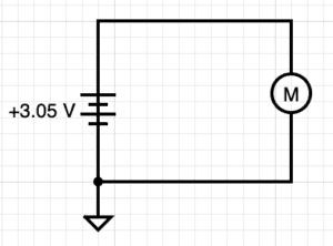
Using a multimeter, measure resistance and voltage with one battery and one motor. With Ohm’s law, calculate the current in the circuit.
Utilizing a multimeter or using indirect measurement, read the real current in the circuit. Read also the voltage applied to the circuit.
Draw an equivalent circuit to your battery-motor circuit. Explain in your own words what makes theoretical and real currents different.
Using this information, calculate the duration that the battery capacity will allow the motor to run in real conditions.
Battery: CR2032 (Datasheet)
Voltage: 3.05 V
Resistance: 6.5 ohm
Ohms Law: 3/6 = 0.5A
Multimeter Current:10.3 mA
Theoretical Current VS Actual Current:
Theoretical current displays the mathematical interpretation of the circuit, which is great for approximations and predictions. However, it cannot account for certain factors such as additional sources of resistance, which could appear in a variety of ways. Poorly connected leads, wire composition, and other components could contribute to effecting the current; Therefore, measuring the actual current with a multimeter allows for more of a precise reading of the circuit.
Battery Duration:
According to the actual current, if it is drawing 10.3 mA, the duration of the battery should be roughly 19 hours. Whereas, if the motor is drawing 500 mA, the duration will be around 25 minutes.
Experiment 2: A moving circuit
Using a soldering iron, pliers, wire cutters and other tools, make a small prototype that has:
- switch
- battery
- motor
Document the process of this small creation, the materials and processes you went through and any information that other roboticists might need to replicate your experiment.
Material list:
- 1 CR2032 Battery
- Battery Casing
- Mini Switch
- Mini circular vibrating motor
- Wires
- Cardboard
- Brass Wire
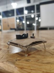
I began constructing my circuit with solely a battery, battery casing, a single motor, and a switch. As minimalistic as it was, it assisted in visualizing the different directions I could move towards with the materials at hand. I soldered the wires together as necessary, creating a simple circuit between the battery, switch, and motor. My next step was constructing some sort of body that would allow these components to stay in place. I could tell that the power provided by the motor was minimal, so I opted to use cardboard as the framework for the device due to its lightweight nature. I continued to attach the components to a small 3x3in of cardboard, leaving the battery and switch visible and the motors and wires pressed behind another 3x3in of cardboard. The result was a cardboard sandwich-like robot, however, it lacked any significant movement. To combat this, I cut a 4in piece of brass wire evenly into 4 pieces and glued them to the bottom of the cardboard, giving the device mini legs and eliminating the cardboard friction. By decreasing the surface friction, the robot moved at a significantly greater pace but lacked movement in any particular direction.
Experiment 3: Iterate
Create a table with at least three different iterations of the robotic structure. You can try with different locomotion methods. Test them under different conditions you think useful for it, such as weight it can curry or different surfaces. Make sure your table include annotations for future analysis.
| Iterations | Results |
| Wooden Table Testing | https://drive.google.com/file/d/10TcJjjNVbieOUGhXxez9VLXVCTbnfBan/view?usp=sharing
As shown in the video above, the robot had difficulty moving while on the wooden table surface. I believe that the grooves in the wood prohibited the robot for moving at its full potential. |
| IMA Floor Testing | https://drive.google.com/file/d/10Rm5xNdzACC7DV2RCIvyUu43J_2SdD99/view?usp=sharing
As shown in this video, the robot functioned best when test on the IMA floor. The smooth surface allowed for the robot to maneuver in random directions at a semi-constant speed. |
| Change of Surface Contact: Brass to Plastic | During the testing face, I decided to add a tad bit of glue to the end of each leg, as I was curious whether it would improve or worsen the mobility of the robot. I contemplated that maybe the brass endings were puncturing the surface too much, however, I discovered that the robot’s functionality was dampened with the glue. I shortly realized that the glue increased the surface friction, in hence slowing down the speed of the robot. |
Experiment 4: Build a light sensor
Use a Light Dependent Resistor to build a circuit that gets activated by the presence (or absence) of light. Hand-draw your circuit and annotate the behavior.
As a help for this step, you might need to do a bit of research on LDR circuits. It might be handy to use http://www.ermicro.com/blog/?p=1097 as a reference.
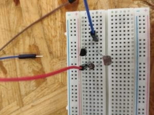
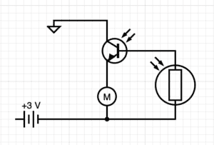
As shown in the photo of the breadboard and circuit diagram above, the electricity traveled from the battery source to the transistor, and if the LDR value was high enough (which depends on the amount of light it receives), the transistor would then release enough current to spin the motor and complete the circuit.