Brainstorm:
As it described in the final project proposal, I decide to continue on the locomotion lab and turtle robot prototype and make a spider robot which imitates spider’s locomotion as my final project. I did not choose spider as my targeted object randomly. After I did some exploration, I found out there is similarity between turtle’s and spider’s locomotion. Following two videos show the locomotion of these two different animals.
As we can see, spider has two times of legs as turtle does. However, when I divide spider’s eight legs into front four and latter four, I surprisingly found out these two sets of legs are moved in roughly the same pattern and it is quite similar to the pattern of turtle locomotion. However, since spiders’ leg has more joints, thus it moves more neatly. Thus, the project can be regarded as an upgrade of the turtle robot prototype.
After I researched for spider robot, I found out there is already an existing project which someone make a four-leg spider robot with Arduino system, 3d-printed models and twelve 9g servos. However, as far as I am capable of, I have no idea of how to do it by using Arduino. But the 3d-printed modes are helpful for me to start the first step.
Since for the whole semester, we are using micro:bit robot:bit and kittenbot to build different things, I decide to try to build the spider robot with micro:bit and robot:bit. Also, one biggest advantage of using robot:bit I believe is that it can easily solve the problem of power 12 servos at the same time. However, one robot:bit can only power 8 servos at the same time, which means I have to use two robot:bit.
Assembly:
The assembly units need to use:
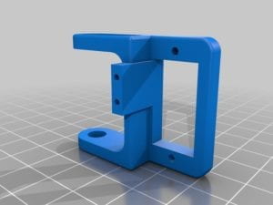
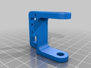
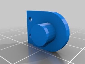
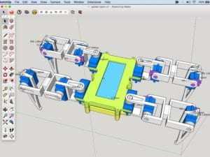
3d-printed spider skeleton (The 3d model was designed by RegisHsu) including:
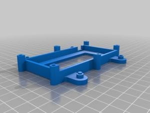
1×body_d
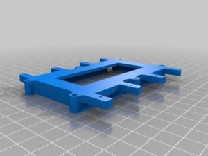
1×body_u
2×coxa_l
2×coxa_r
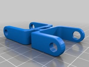
4×femur
8×hold
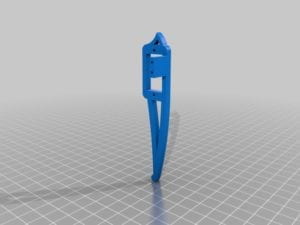
2×tebia_l
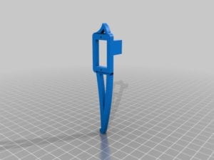
2×tebia_r
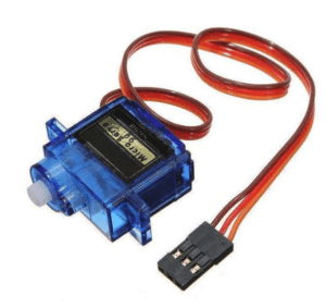
12×sg90 9g servo
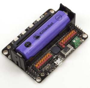
2×robot:bit (for Kittenbot)
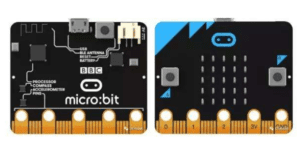
4×micro:bit
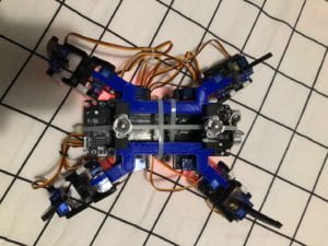
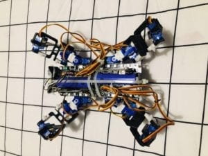
I guess waiting for all the models printed out is the longest step in the whole project. After a more than 10-hour-printing process(well I have to say school’s 3d printers do not function so well), I finally got and 3d-printed parts. So that, I can assemble the robot according to the blueprint.
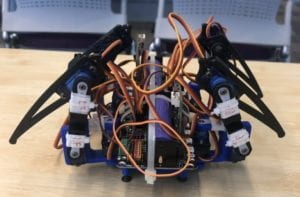
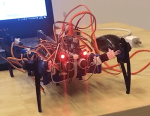
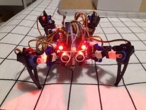
However, since I will do the project with robot:bit instead of Arduino, I have to figure it out how to put two robot:bit properly. Luckily, the body part has just fine space to arrange two robot:bit, but it will affect all four legs, which means all four legs cannot turn to be parallel to the body in this situation. It may affect the final product, but I still decide to try. After Rudi’s helping me by using zip tie to tie two robot:bit on the body, I finally succeeded in assembling all parts so far together. The spider robot I have done is displayed below.
First Problem – 3D-printed units:
Apart from the failure of 3d printers, the first problem I met is about the 3d-printed units. Due to limitation of 3d-printer techniques or the fulfillment of 3d-printer, the units I got have fine deviation, which mean not all parts can assemble together as it should be. I have to use drills to fix this problem, though it is just a small problem.
Second Problem – Servo Calibration:
When I was so happy that I have assemble all the units together and I can focus on the coding part, I found that servos did not work as I thought. Some start at a weird place and and some never go to the place I want them be. After searching for the working principles of servos, I found out that I did not calibrate them to 0 degree before I assemble. There is no other ways so I have to separate all units. Then I use micro:bit to calibrate all the servos to 0 degree since it will be the most precise way. Also, during the process, I record some data such as the degrees which servo are at horizontal position and the degrees that servos can turn at maximum according to the pins these servos connected to. These data will be helpful when I do the coding.
Sparkle:
When I have assembled the body and legs, I found out he robot is almost symmetric from appearance. It will add difficulty when I do the coding. Thus I decide to assemble a head to it. At first, I try to attach whatever something round to the body. Then I suddenly thought about the ultrasonic module of the Kittenbot. To be honest, at first, I just think about the RGB led lights on it. Some of the spiders have red eyes, so If I add it to the robot and make lights red. The robot will be more like a spider and super cool. Then a sparkle suddenly come out to me that even the ultrasonic function can be used.
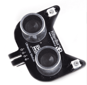
1×Ultrasonic module
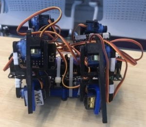
On the first half of the semester, I have done the Kittenbot which can detect obstacles by using ultrasonic. It is also possible to achieve that on the spider robot. So I connect the module by using zip tie to one side of the body and make it the head side. The product is displayed below.
Third Problem – Weight:
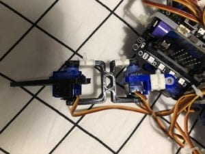
The existing four-leg spider robot done by using Arduino obviously does not have such problem. However, since I use two robot:bit instead of Arduino, the weight is over the expectation. Even there are 12 servos, then can only hold the body when all four legs are stand on the ground. When I try to move a leg in the air, three leg failed to hold the weight of the body and the spider hit the ground. The solution I gave is to attach the body to the ground to relief legs’ pressure. But the junction point must has little or no fraction so that it would not affect spider’s movement. Thus I thought about the Omnidirectional wheels on the Kittenbot.
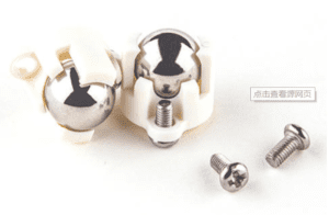
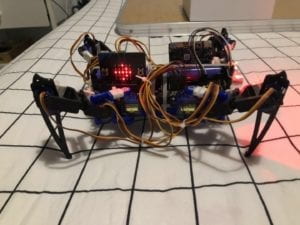
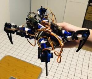
2×Omnidirectional wheel
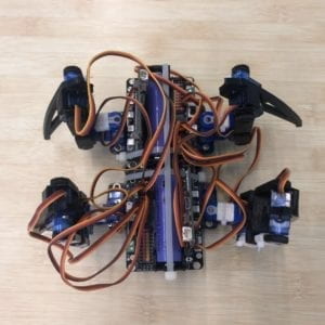
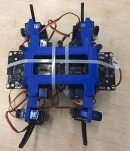
Since the Omnidirectional wheels are not high enough, I used eraser to increase height and tie the eraser and the wheel to the body with zip tie. Till now, I have done all the assembly work of the four-leg spider robot. The final product is displayed below:
Coding:
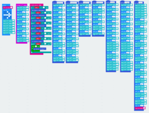
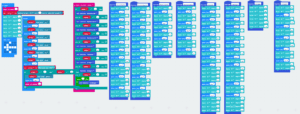
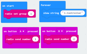
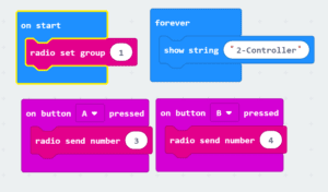
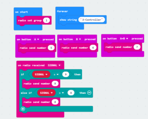
The coding is all done by using Makecode. I will use three micro:bit as controller. Following is the code I wrote for the project.
Right Side:
Left Side:
Three Controllers:
The code I have written can be divided into Six parts: Startup, Straight Line Movement Pattern 1, Straight Line Movement Pattern 2, Veer Movement, Obstacle Avoidance, and a Stinger. I guess my following description of the patterns is hard to understand, but I have record several videos for each type of movement. I believe it will be much easier to understand through video.
Start up:
No matter what its beginning posture, when the power of micro:bit turns on, it will turn to a stand posture.
Straight Line Movement Pattern 1:
The spider robot moves forward one foreleg on one side and one hind leg on the other side in the air. Then, similarly, it moves forward the rest two legs in the air. Finally, the joints of four legs to the body move forward. Due to the fraction between legs and the ground, the robot body will move forward. Reversely, the robot can achieve backward movement. The biggest feature of this pattern is that four legs will offer fraction at the same time to move the body.
Forward:
Backward:
Straight Line Movement Pattern 2:
Another pattern is that the robot moves forward one foreleg on one side and one hind leg on the other side in the air while the joints which connect the rest two legs to the body will move forward at the same time. The robot will move forward due to the fraction offered by the two legs which stand on the ground. Reversely, the robot can achieve backward movement. The main difference between pattern 1 and pattern 2 is that pattern 2, at the same time, only has two legs offer fraction which move its body forward while pattern 1 has four.
Forward:
Backward:
Veer Movement:
Veer is the easiest locomotion pattern to achieve. The robot moves one foreleg on one side and one hind leg on the other side in one direction in the air. Then it moves the rest two legs in the same direction. After that, four joints will move towards the same direction. Due the fraction between four legs and the ground, legs will stay at the same position. But the body will veer in the direction that you move the legs.
Turn left:
Turn right:
Obstacle Avoidance:
Once the spider robot sense obstacle in its by using ultrasonic senses, it will turn right.
Stinger:
At last, Let’s have fun!
Comparing Straight Line Movement Patterns:
Both of the two straight movement patterns can help the robots move forward and backward. However, each of them has their own advantages and disadvantages
If we compare them from the perspective of Biology, pattern will definitely be a better and more biomimetic option. Pattern 2 is closer to a regular way of how animals which have four legs crawl. Barely has animals use the first pattern to move.
However, if we consider the problem of stability, pattern 1 is a better choice. The most obvious reason is that pattern 1 uses four legs to offer fraction at the same time while pattern 2 uses only two. The actual results also prove this standpoint. When the spider robot uses pattern 1 to move, it always walks a straight line under most circumstances. However, when it uses pattern 2 to move, it easily deviate from straight line.
Flaws:
Honestly speaking, the four-leg spider robot is far from perfect. There are still a lot of places can be improved. For example, the body is too heavy for the servos even there 12 of them. Also, it is hard for the straight line movement pattern 2 to walk a straight line. But I strongly doubt it is hardware problem. The robot always turn right. It means that left side offers stronger fraction than right side. I guess the problem is possible to solve.
Reflection:
As a finance major student, I never expect one day I will do this kind of project at school. It is definitely a meaningful project to me as I have done a not bad project from nothing. During the project, I learned always endeavoring to do still better. The innovation ability and thinking capability is what more important I get from this class. I believe these things are more precious than simply how to do a robot and I really appreciate about it.