Recitation 8: Serial Communication by Xueping

Etch A Sketch (ellipse)

This device/toy basically turns movement into visualized figures which enables users to think and create drawings via spinning the knob. This interaction is meaningful and provides great individual experience so that users are involved in this game.
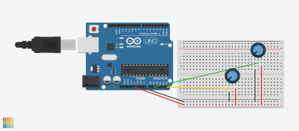
diagram 1

Code for Arduino – Etch A Sketch 

https://github.com/LilyWang1997/BeHappy/compare/master…LilyWang1997-recitation-8?expand=1#diff-b6f2cc785ca65c1eebad1297a4739d11

Code for Processing – Etch A Sketch (ellipse)

// IMA NYU Shanghai
// Interaction Lab
// For receiving multiple values from Arduino to Processing

/*
 * Based on the readStringUntil() example by Tom Igoe
 * https://processing.org/reference/libraries/serial/Serial_readStringUntil_.html
 */

import processing.serial.*;

String myString = null;
Serial myPort;


int NUM_OF_VALUES = 2;   /** YOU MUST CHANGE THIS ACCORDING TO YOUR PROJECT **/
int[] sensorValues;      /** this array stores values from Arduino **/


void setup() {
  pixelDensity(2);
  size(500, 500);
  background(0);
  setupSerial();
}


void draw() {
  updateSerial();
  printArray(sensorValues);
  ellipse(sensorValues[0], sensorValues[1], 100,100);
  // use the values like this!
  // sensorValues[0] 

  // add your code

  //
}


void setupSerial() {
  printArray(Serial.list());
  myPort = new Serial(this, Serial.list()[ 5 ], 9600);
  // WARNING!
  // You will definitely get an error here.
  // Change the PORT_INDEX to 0 and try running it again.
  // And then, check the list of the ports,
  // find the port "/dev/cu.usbmodem----" or "/dev/tty.usbmodem----" 
  // and replace PORT_INDEX above with the index number of the port.

  myPort.clear();
  // Throw out the first reading,
  // in case we started reading in the middle of a string from the sender.
  myString = myPort.readStringUntil( 10 );  // 10 = '\n'  Linefeed in ASCII
  myString = null;

  sensorValues = new int[NUM_OF_VALUES];
}


void updateSerial() {
  while (myPort.available() > 0) {
    myString = myPort.readStringUntil( 10 ); // 10 = '\n'  Linefeed in ASCII
    if (myString != null) {
      String[] serialInArray = split(trim(myString), ",");
      if (serialInArray.length == NUM_OF_VALUES) {
        for (int i=0; i<serialInArray.length; i++) {
          sensorValues[i] = int(serialInArray[i]);
        }
      }
    }
  }
}

Etch A Sketch (REAL)

Code for Processing – Etch A Sketch (REAL)

import processing.serial.*;

String myString = null;
Serial myPort;


int NUM_OF_VALUES = 2;   /** YOU MUST CHANGE THIS ACCORDING TO YOUR PROJECT **/
int[] sensorValues;      /** this array stores values from Arduino **/
int[] psensorValues = {0,0};

void setup() {
  //pixelDensity(2);
  size(600, 600);
  background(0);
  setupSerial();
  printArray(sensorValues);
  //arrayCopy(sensorValues, psensorValues);
  
}


void draw() {
  updateSerial();
  printArray(sensorValues);
  strokeWeight(1);
  stroke (255);
  line(psensorValues[0], psensorValues[1], sensorValues[0], sensorValues[1]);
  psensorValues[0] = sensorValues[0];
  psensorValues[1] = sensorValues[1];
  // use the values like this!
  // sensorValues[0] 

  // add your code

  //
}


void setupSerial() {
  printArray(Serial.list());
  myPort = new Serial(this, Serial.list()[ 5 ], 9600);
  // WARNING!
  // You will definitely get an error here.
  // Change the PORT_INDEX to 0 and try running it again.
  // And then, check the list of the ports,
  // find the port "/dev/cu.usbmodem----" or "/dev/tty.usbmodem----" 
  // and replace PORT_INDEX above with the index number of the port.

  myPort.clear();
  // Throw out the first reading,
  // in case we started reading in the middle of a string from the sender.
  myString = myPort.readStringUntil( 10 );  // 10 = '\n'  Linefeed in ASCII
  myString = null;

  sensorValues = new int[NUM_OF_VALUES];
}


void updateSerial() {
  while (myPort.available() > 0) {
    myString = myPort.readStringUntil( 10 ); // 10 = '\n'  Linefeed in ASCII
    if (myString != null) {
      String[] serialInArray = split(trim(myString), ",");
      if (serialInArray.length == NUM_OF_VALUES) {
        for (int i=0; i<serialInArray.length; i++) {
          sensorValues[i] = int(serialInArray[i]);
        }
      }
    }
  }
}

Musical Instrument

This is kind of a new musical instrument though the interaction and outcome is pretty simple. By moving the mouse on the canvas, the tones change. It can be quite interesting, but for me this game is a bit boring as the interaction is too simple.
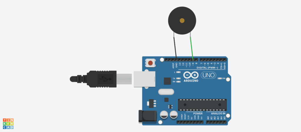
diagram 2

Code for Arduino – Musical Instrument

https://github.com/LilyWang1997/BeHappy/compare/master…LilyWang1997-recitation-8?expand=1#diff-b6f2cc785ca65c1eebad1297a4739d11

Code for Processing – Musical Instrument

import processing.serial.*;

int NUM_OF_VALUES = 2;  /** YOU MUST CHANGE THIS ACCORDING TO YOUR PROJECT **/


Serial myPort;
String myString;

// This is the array of values you might want to send to Arduino.
int values[] = new int[]{0,0};
int x;
int y;
void setup() {
  size(500, 500);
  background(0);

  printArray(Serial.list());
  myPort = new Serial(this, Serial.list()[ 5 ], 9600);
  // check the list of the ports,
  // find the port "/dev/cu.usbmodem----" or "/dev/tty.usbmodem----" 
  // and replace PORT_INDEX above with the index of the port

  myPort.clear();
  // Throw out the first reading,
  // in case we started reading in the middle of a string from the sender.
  myString = myPort.readStringUntil( 10 );  // 10 = '\n'  Linefeed in ASCII
  myString = null;
}


void draw() {
  background(0);
  x = mouseX;
  map(x,0,600,0,255);
  y = mouseY;
  map(y,0,600,0,255);
   
  // changes the values
  for (int i=0; i<values.length; i++) {
    values[0] = x;  /** Feel free to change this!! **/
    values[1] = y; 
  }

  // sends the values to Arduino.
  sendSerialData();

  // This causess the communication to become slow and unstable.
  // You might want to comment this out when everything is ready.
  // The parameter 200 is the frequency of echoing. 
  // The higher this number, the slower the program will be
  // but the higher this number, the more stable it will be.
  echoSerialData(200);
}

void sendSerialData() {
  String data = "";
  for (int i=0; i<values.length; i++) {
    data += values[i];
    //if i is less than the index number of the last element in the values array
    if (i < values.length-1) {
      data += ","; // add splitter character "," between each values element
    } 
    //if it is the last element in the values array
    else {
      data += "n"; // add the end of data character "n"
    }
  }
  //write to Arduino
  myPort.write(data);
}


void echoSerialData(int frequency) {
  //write character 'e' at the given frequency
  //to request Arduino to send back the values array
  if (frameCount % frequency == 0) myPort.write('e');

  String incomingBytes = "";
  while (myPort.available() > 0) {
    //add on all the characters received from the Arduino to the incomingBytes string
    incomingBytes += char(myPort.read());
  }
  //print what Arduino sent back to Processing
  print( incomingBytes );
}
Recitation 1: Electronics

Introduction

For this recitation, I had to build 3 basic circuits using the different components of Arduino.

Materials

  • 1 * Breadboard
  • 1 * LM7805 Voltage Regulator
  • 1 * Buzzer
  • 1 * Push-Button Switch
  • 1 * Arcade Button
  • 1 * 220 ohm Resistor
  • 1 * 10K ohm Resistor
  • 1 * 10K ohm Variable Resistor (Potentiometer)
  • 1 * LED
  • 1 * 100 nF (0.1uF) Capacitor
  • 1 * 12 volt power supply
  • 1 * Barrel Jack
  • 1 * Multimeter
  • Several Jumper Cables (Hook-up Wires)

Circuit 1: Doorbell

For this circuit I had to make a doorbell using a buzzer and a button so that when the button is pressed, the circuit is completed creating the buzzer sound.


Circuit 2: Lamp

In the second circuit, similar to the first, I had to create a “lamp” using an LED light. Creating this circuit only meant replacing the buzzer with an LED. The button was also there so that when it was pressed, the LED would turn on.


Circuit 3: Variable Lamp

For the third circuit, I attached a potentiometer and let Arduino read its values. I connected the LED to a PWM input which let it read analog signals, and by doing so, I was able to control the brightness of the LED using the potentiometer.

Questions:

1) Circuit interactivity

  • In its most basic form, these circuits were interactive because of the use of the button and the potentiometer— I press a button and the light turns on, or I twist a knob which controls the brightness of the light.

2) Interaction in art

  • Art itself is meant to grab people’s attention. Interactivity can be used as a very effective tool in attracting people towards the art. Art in the traditional sense is meant to be looked at, however, if the viewer were to be part of the art viewing experience, being able to change the art itself with their interaction, then people will be more likely to be interested in it. Using the Wooden Tile Mirror as an example, the viewer is able to project their physical form onto a mirror created with wooden tiles. This creates an abstract image of the viewer, changing the art viewing experience.

Recitation 4: Drawing machines by Tya Wang (rw2399)

Materials:

1 * 42STH33-0404AC stepper motor
1 * L293D ic chip
1 * power jack
1 * 12 VDC power supply
1 * Arduino kit and its contents

2 * Laser-cut short arms
2 * Laser-cut long arms
1* Laser-cut motor holder
2 * 3D printed motor coupling
5 * Paper Fasteners
1 * Pen that fits the laser-cut mechanisms
Paper

Step 1: Build the circuit

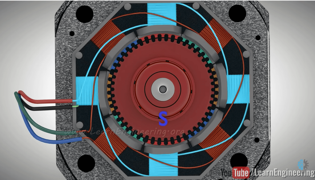
For step 1, I assembled everything according to the diagram in a minute because we’ve had so much experience in wiring up H-bridges. However, I have to admit that I never thoroughly figured out why the cables need to be connected this way. And although I have a blurred memory that we have talked about why the H-bridge controls the rotation direction in class, I am still not sure why it worked this way. So, I read through web pages and documents on the electronic parts, and I learned that a stepper motor functions following the change of electromagnetic signals.

As shown in the picture above, electricity magnetizes set 1A and 2A, flowing through the red and black wires, and set 4A and 3A, flowing through the green and blue wires,  in turn to attract or repulse the rotor and make it rotate. When electricity flows in the other direction, the rotation direction of the stepper will also change.

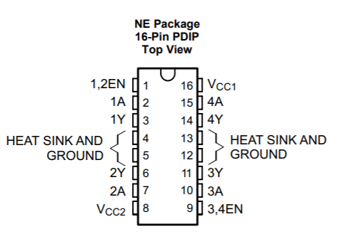
The turns between the sets are controlled by the H-bridge, giving high and low signals to pins 1-4A. And while we give 5V power to pins 1-4EN to activate pins 1-4A, electricity into V(CC1) is used to power the H-bridge itself, and that into V(CC2) is giving power to the stepper. That’s why we give different power to pins 1, 8, 9, 16 in the picture above, and the step motor has 4 wires attached to it.

After uploading the stepper code, the rotation direction is changing constantly.

Step 2: Control rotation with a potentiometer

If I want to control the angle of rotation based on the angle I turned the knob, I need to map the value returned by the potentiometer to the step of the stepper. Here is the revised code:

#include <Stepper.h>
#define STEPS 200
Stepper stepper(STEPS, 8, 9, 10, 11);
int previous = 0;

void setup() {
  stepper.setSpeed(30);
}

void loop() {
  int val = map(analogRead(0), 0, 1023, 0, 200);
  stepper.step(val - previous);
  previous = val;
}

Step 3: Build a Drawing Machine!

While I was assembling the machine, I found that the hands and the base are all laser-cut from the lab. I was amazed by how much the simple parts are capable of when they are properly organized and designed–with a basic stepper hooked on Arduino and the common paper clips,  such an interactive device that draws out patterns is manufactured. I had great fun watching these two discs turning on my command and dragging the hands with them.

Documentation:

Question 1:

What kind of machines would you be interested in building? Add a reflection about the use of actuators, the digital manipulation of art, and the creative process to your blog post.

I am interested in building a machine that is pleasant to look at and fun at the same time. In the Papier project, not only are the patterns on the paper artistic, the device is also working perfectly as toys. Both of these two factors would make a machine cater to the need of its potential users aesthetically and pragmatically. 

The actuators are the fundamental part of a machine if the designer intended to have the machine fulfill its job by moving. The more delicate the movement of an actuator, the better job the machine can accomplish. However, when I was reading the articles assigned for week five, it was unexpected for me to see that some small devices that involve using actuators are not electronic. A lot of toys takes energy when human touches or play with them. Also, a lot of Automata in the articles have the actuators exposing to the viewers. I always thought that putting the gears inside a device is a rule for machine designers because they are believed to be fragile and to mechanical to look at. When I think about it, I realized that they make much sense because when people watch the functioning of machines through its exposed inside organization, they can have a deeper understanding of the devices. And for children who play with these toys, it is also fun and inspiring when they see the parts moving to his movements.

Although in this recitation I built a machine that draws, I do not think that art in the future should be taken over by computers and artificial intelligence, because somehow I think that art or beauty is the deepest feeling of humanity, and should be exclusive to the naturally developed consciousness. However, I am not against using computers to assist the production of an idea because machines are tools for us and we better make the best use of them. For example, when an artist designs a sculpture, 3D printers can make the technique of carving materials not a limitation to him. Therefore, while an idea should be original, the process of realizing the idea can be assisted.

Question 2:

Choose an art installation mentioned in the reading ART + Science NOW, Stephen Wilson (Kinetics chapter). Post your thoughts about it and make a comparison with the work you did during this recitation. How do you think that the artist selected those specific actuators for his project?

The piece Fish, Plant, Rack created by Andy Gracie shows the communication between the three parties and how they help each other in surviving in a system. The fish in an aquarium sees the situation of the plant’s growth, and the robot reads its electric discharges to care for the plant. I think this design is brilliant because while it involves the aspect that computers are capable of and human beings are not, it also shows how machines can be integrated in the world of lives and help them live. When compared with what I’ve been doing in this recitation, I think the main difference is that while my device creates art in a random manner, Gracie’s device reads information from real life and brings a change to it. I really like his choice of actuators because in the photo, the robot seems to be moving smoothly in an environment filled with water. And I think the shape of the tube growing these plants has also made it harder for the actuators to move in between them.

Recitation 8: Serial Communication – Zhao Yang

Exercise 1:

For this exercise, we were required to use Arduino to send values to Processing. We had done some similar exercises during classes before this recitation class, so this exercise was not too difficult to complete. When we do the first part of this exercise that control the position of the circle, the circle would move out of the canvas if I directly use the values from the Arduino. Thus, I had to map the value between 0 and 500. As I moved to the second part to make the Etch A Sketch work, I found the difficulty to store the previous values of x coordinate and y coordinate. In this case, I reread the original code and found that I just needed to assign these two values before the updateValue function. Finally, I created another Etch A Sketch by using Arduino and Processing. But I cannot draw as well as what the video showed. 

Exercise 2:

The second exercise required us to use Processing to send values to Arduino. We used the buzzer as the output of the exercise. And the values which were sent were the x coordinate and the y coordinate of the mouse, which are assigned as the frequency of the tone and the duration of the tone. At first, the tone would change as soon as you moved the mouse. Then, I added the interaction with the keyboard. In this case, only when you press the space key on the keyboard can the tone change. Since the tone wouldn’t change continuously, you can even play some melodies by moving the position of the mouse and pressing the space key. Maybe in the future, I would add more interactions with the keyboard to make it more interesting. 

Code:

https://github.com/JooooosephY/Recitation-8

Recitation 8: Serial Communication – Audrey Samuel

During last week’s recitation, we were required to use Serial Communication to send data from Arduino to Processing and vice versa. This was a lot of work and it took quite some time before I was able to correctly input the right code. I found myself getting confused as to when certain lines of code should be typed in Arduino and when they should be typed in Processing but overall it was a success! 

Exercise 1:

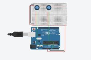
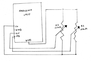
For this exercise we were asked to use Arduino to send two analog values to Processing. I first built my circuits with two potentiometers and connected this to my Arduino board. I had to keep in mind which pins I was using (ie. A0 and A1). After I had built my circuit I opened up the example code given to us and looked at how I could edit it. I first opened the “multiple values from Arduino to Processing” on Arduino and made sure I had only two sensors and that they were defined in my local variables underneath void loop(). I then opened up Processing and made sure I had changed the number of values to 2 since I was using only two sensors. I also had to change my Serial.list number to [1] depending on the order of my ports, which our professor showed us how to do in class. I then began to draw my two ellipsis that I would control with my potentiometers on Processing. I set up the size under void setup() and began to draw the ellipse under void draw(). I got some help from the learning assistants and learnt that I could write this code as “ellipse(sensorValues[0], sensorValues[1],50,50)” as I had already defined my sensor variables earlier. This made it easier to work with. I also set the background to black so that I could see the circle moving. The potentiometers worked and moved the circle based on its x and y positions. 

Circuit 1 Schematic

After I drew the circle, I was required to change this to a line and create a drawing similar to “etch a sketch”. I learnt that for this I would have to define new variables (previousX and previousY) so that my line would start drawing from its previous point each time I turned the potentiometer. Under void draw() I drew the line with the code: “line(previousX, previousY, sensorValues[0], sensorValues[1]).” I also had to make sure I equated the two “previous” variables to the appropriate “sensorValue” variables. This was quite interactive as I was designing my own etch a sketch on Processing using two potentiometers through Arduino. 

Exercise 2:

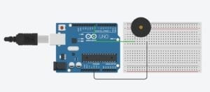
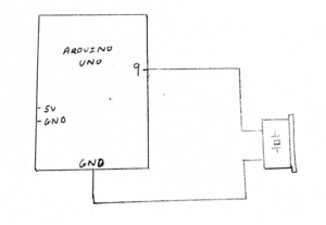
For the second exercise we were required to make a processing sketch that sends values to my Arduino based on my mouse’s x and y position. I had to make sure the Arduino code could read the serial values from Processing and translate this into music which would be heard through the buzzer. I had to use the tone() function to this exercise. I copied over the pitches.h file from tone() and inserted it into a new tab within my “multiple values from Processing to Arduino” code on Arduino. I then went to the main code and typed in #include “pitches.h” to let Arduino know I wanted my melody taken from that file. I also copied over the notes I wanted to be played. Next, I made a circuit and made sure my buzzer was connected to digital pin 9 on my Arduino. I then included this under void setup(). Under void loop() I only used the example code provided for “tone”.  I had to modify which sensorValues I was using. I then went to Processing and edited the code so it had 2 sensors and the appropriate Serial.list number. I then included an if function under void draw() which stated that if (mousePressed) values[0] = 1; else values[0] = 0.I also defined Values [1] = mouseX. This allowed me to change the sound emitted from the buzzer depending on where my mouse was placed on the x-axis in processing. I did the same for mouseY. This was interactive as I had to click on Processing using my mouse in order for sound to play from my buzzer through Arduino.

Circuit 2 Schematic