Recitation 8: Serial Communication by Yu Yan (Sonny)

Introduction:

In this recitation, we worked on building communication between Arduino and Processing. The first exercise is to use Arduino to send data to Processing, for Arduino is the input and Processing is the output. The second exercise is to use Processing to send data to Arduino, for Processing becomes the input and Arduino is the output. Through these two practises, I get more familiar with building the connection between Arduino and Processing via serial communication.

Exercise 1:

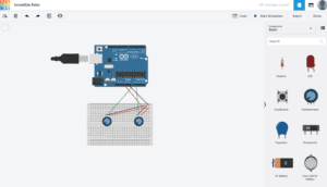
The first exercise is to make an Etch A Sketch. For this exercise, the input is two potentiometers from Arduino, and the output is the canvas of Processing. I used two potentiometers to control the position of the “pen”, then rotated them to make a sketch on Processing. Before making an actual sketch, I followed the instruction to draw an ellipse first. I practised this in previous classes, so this step is easy for me. I created two variables to stand for the values of x-axis and y-axis. I also used the “map” to keep the ellipse move inside the canvas, since the biggest value of the potentiometer is 1023, while the limit of width and height of the canvas is only 500. Then I modified the Processing code and turned the ellipse into a line. To do this, I used a sample code from a previous class as a reference, which is about using the mouse’s movement to draw a line. In order to make a “real” Etch a Sketch, I need to keep track on the previous x and y values as well. So I added two more variables that stand for previous x and y. I defined them as x and y in the “draw()” loop which were after the “line()”, so they can be stored in the previous values of x and y. 
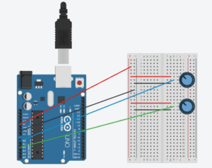
The code for Processing and Arduino is as followed. 

Processing:

import processing.serial.*;

String myString = null;
Serial myPort;

int NUM_OF_VALUES = 2;   /** YOU MUST CHANGE THIS ACCORDING TO YOUR PROJECT **/
int[] sensorValues;      /** this array stores values from Arduino **/
float x;
float y;
float px;
float py;

void setup() {
  size(500, 500);
  background(0);
  setupSerial();
}

void draw() {
  //background(0);
  updateSerial();
  printArray(sensorValues);
  x = map(sensorValues[0], 0, 1023, 0, 500);
  y = map(sensorValues[1], 0, 1023, 0, 500);
  stroke(255);
  line(px,py,x,y);
  px = x;
  py = y;
}

void setupSerial() {
  printArray(Serial.list());
  myPort = new Serial(this, Serial.list()[0], 9600);

  myPort.clear();
  myString = myPort.readStringUntil( 10 ); 
  myString = null;

  sensorValues = new int[NUM_OF_VALUES];
}

void updateSerial() {
  while (myPort.available() > 0) {
    myString = myPort.readStringUntil( 10 ); // 10 = '\n'  Linefeed in ASCII
    if (myString != null) {
      String[] serialInArray = split(trim(myString), ",");
      if (serialInArray.length == NUM_OF_VALUES) {
        for (int i=0; i<serialInArray.length; i++) {
          sensorValues[i] = int(serialInArray[i]);
        }
      }
    }
  }
}

Arduino:

void setup() {
  Serial.begin(9600);
}

void loop() {
  int sensor1 = analogRead(A0);
  int sensor3 = analogRead(A2);

  Serial.print(sensor1);
  Serial.print(",");
  Serial.print(sensor3);
  Serial.println();
  delay(100);
}

Exercise 2:

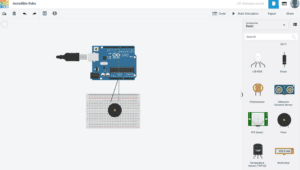
The second exercise is to make a musical instrument. For this exercise, the input is the mouse’s movement in Processing, and the output is the buzzer on Arduino board. In order to do this, I only made a few changes to the sample code. I used the mouse’s x and y positions to control frequency and duration of the tone. Since the buzzer can only make a sound when the frequency is bigger than 31, I used the “map” to keep the frequency in the range of 200 and 2000. I also used “mousePressed()” to set the pressing of the mouse to control the on and off of the sound. On this basis, I made some improvements to the original canvas. I modified the Processing code so that the canvas would change the color when I press the mouse and turn to black when I release my mouse. In this way, you can visually see that you are playing with this musical instrument.
The code for Processing and Arduino is as followed.

Processing:

import processing.serial.*;

int NUM_OF_VALUES = 3; 
int x;
int y;
color c;
float h = 0;

Serial myPort;
String myString;

int values[] = new int[NUM_OF_VALUES];

void setup() {
  size(500, 500);
  colorMode(HSB,360,100,100);
  background(360);

  printArray(Serial.list());
  myPort = new Serial(this, Serial.list()[0], 9600);

  myPort.clear();
  myString = myPort.readStringUntil( 10 );  // 10 = '\n'  Linefeed in ASCII
  myString = null;
}

void draw() {
  background(360);
  c = color(h,100,100);
  if (mousePressed){
    h += 1;
    background(c);
    if (h > 360){
      h = 0;
    }
  } else {
    background(0,0,0);
  }

  x = mouseX;
  map(x,0,500,200,2000);
  y = mouseY;
  map(y,0,500,100,1000);

  values[0] = x;
  values[2] = y;

  
  if (mousePressed == true){
    values[1] = 1;
  } else {
    values[1] = 0;
  }
  
  sendSerialData();
  echoSerialData(200);
}

void sendSerialData() {
  String data = "";
  for (int i=0; i<values.length; i++) {
    data += values[i];
    //if i is less than the index number of the last element in the values array
    if (i < values.length-1) {
      data += ","; // add splitter character "," between each values element
    } 
    //if it is the last element in the values array
    else {
      data += "n"; // add the end of data character "n"
    }
  }
  //write to Arduino
  myPort.write(data);
}

void echoSerialData(int frequency) {
  //write character 'e' at the given frequency
  //to request Arduino to send back the values array
  if (frameCount % frequency == 0) myPort.write('e');

  String incomingBytes = "";
  while (myPort.available() > 0) {
    //add on all the characters received from the Arduino to the incomingBytes string
    incomingBytes += char(myPort.read());
  }
  //print what Arduino sent back to Processing
  print( incomingBytes );
}

Arduino:

#define NUM_OF_VALUES 3    /** YOU MUST CHANGE THIS ACCORDING TO YOUR PROJECT **/
/** DO NOT REMOVE THESE **/
int tempValue = 0;
int valueIndex = 0;
/* This is the array of values storing the data from Processing. */
int values[NUM_OF_VALUES];

void setup() {
  Serial.begin(9600);
  pinMode(9, OUTPUT);
}

void loop() {
  getSerialData();

  if (values[1] == 1) {
    tone(9, values[0],values[2]);
  } else {
    noTone(9);
  }
}

//recieve serial data from Processing
void getSerialData() {
  if (Serial.available()) {
    char c = Serial.read();
    //switch - case checks the value of the variable in the switch function
    //in this case, the char c, then runs one of the cases that fit the value of the variable
    //for more information, visit the reference page: https://www.arduino.cc/en/Reference/SwitchCase
    switch (c) {
      //if the char c from Processing is a number between 0 and 9
      case '0'...'9':
        //save the value of char c to tempValue
        //but simultaneously rearrange the existing values saved in tempValue
        //for the digits received through char c to remain coherent
        //if this does not make sense and would like to know more, send an email to me!
        tempValue = tempValue * 10 + c - '0';
        break;
      //if the char c from Processing is a comma
      //indicating that the following values of char c is for the next element in the values array
      case ',':
        values[valueIndex] = tempValue;
        //reset tempValue value
        tempValue = 0;
        //increment valuesIndex by 1
        valueIndex++;
        break;
      //if the char c from Processing is character 'n'
      //which signals that it is the end of data
      case 'n':
        //save the tempValue
        //this will b the last element in the values array
        values[valueIndex] = tempValue;
        //reset tempValue and valueIndex values
        //to clear out the values array for the next round of readings from Processing
        tempValue = 0;
        valueIndex = 0;
        break;
      //if the char c from Processing is character 'e'
      //it is signalling for the Arduino to send Processing the elements saved in the values array
      //this case is triggered and processed by the echoSerialData function in the Processing sketch
      case 'e': // to echo
        for (int i = 0; i < NUM_OF_VALUES; i++) {
          Serial.print(values[i]);
          if (i < NUM_OF_VALUES - 1) {
            Serial.print(',');
          }
          else {
            Serial.println();
          }
        }
        break;
    }
  }
}
Final Project Proposal – Stephanie Anderson – 006

Sort your Trash; Save the World

Sort Your Trash; Save the World is a project with an intended purpose to help people better understand how to sort their trash. While many people do not see the effects in the short-term, the long-term effects of their carelessness will more than likely end in the destruction of the Earth and, consequently, the human race (not to be dramatic). In collaboration with Salome, we aim to create a project with an educational purpose of having a fun and interactive way for people (I say people broadly to mean people of ALL ages) to learn how to sort their trash. 

Final Schematic Design

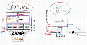
Above, I have posted my design idea. The interface will appear as that of an arcade-style game.  There will be a screen behind the game that will act as a display. Here, cards will pop up with an image and the name of the item. Next to the cards will be a globe that will appear as a bomb with a fuse slowly getting shorter and shorter. The aim of the game is to sort x number of cards before the Earth explodes. The beginning of the game will start with the user selecting, 10, 20, 30, or 40 cards to sort in 30 seconds. You will be able to choose the number based on which can lid you close. Each bin (there are 4) will have a light sensor at the bottom. When you close the lid, the sensor will sense “darkness” and this range will be used to select. There will be a countdown and the game will begin. An image will appear and then you must close the lid or open the lid depending on if that is the appropriate bin. Your score count will increase as you get more and more correct. You will have three strikes. The first time you try to sort one item incorrectly, then a BIG red “X” will appear on the screen and you have to try again. Once you get 3 red “X”s then the bins will fall forward and you will have lost the game. If you are able to get the number sorted in time, then the same level used to slam the bins forward, will push the button to defuse the bomb. 

If we have adequate time and are able to complete the project this far, I would like to implement a “progress” page that will show the cards you sorted incorrectly and tell you which bin to place them in. 

Here is the master schedule for our plan of attack:

Sunday Monday Tuesday Wednesday Thrursday Friday Saturday
        21

final proposal

22 23


24

design playing field: bins/ box/ gear

25

print/create game field

26

design “ticking time bomb globe”

27

print/create game field

28

steph away

card design

29

steph away

card design

30

steph away

card design

1

draft circuit

2

assemble: sensors/ bins

3

assemble: sensors/ bins

4

code: sensors/ bins

5

assemble: gears / button

6

code: interface for game on screen

7

have project finished

8 9 10

project due

11 12

blog post

13 14

Basically, the first week will be designing the physical aspect of our project as well as the images that will be displayed. If they are simple, then we can figure out how to create them ourselves as doodles in Processing, or we can import images into a library. The second week will be coding and assembly week. We will make our circuits as well as coding the interface for our device. 

From the projects that I have researched (such as the Interactive Walls), interactive design projects tend to be the most successful when people are smiling. In Daniel Shiffman’s book, Learning Processing – while the majority of the book is written about coding certain examples for processing – one of the chapters entitled, “The World Revolves Around You,”  emphasizes the reason for doing your projects. For me, if your device can make someone smile, then I think you have accomplished your task. We will accomplish this through stylish interface as well as an aesthetically pleasing physical design that the users enjoy touching and manipulating. I think something we need to be careful of is that often times with projects like these, they are not built very strong; this means that you as the designer are worried every time someone touches your project that a wire will become loose or something falls off. I want to build this project in confidence of my design and of 100% accuracy. While trashing sorting is currently an on-going affair in China, it should be a more commonly done practice around the world. The overall goal of having this device is to show people how easy it is to sort your trash if you just take a few seconds to do it correctly. 

Sources:

Shiffman, Daniel. Learning Processing : A Beginner’s Guide to Programming Images, Animation, and Interaction, Elsevier Science & Technology, 2015. ProQuest Ebook Central, https://ebookcentral-proquest-com.proxy.library.nyu.edu/lib/nyulibrary-ebooks/detail.action?docID=4003651.

Final Project Step 3 Essay

Sortinator

After discussing our six project ideas with my project partner, we decided on one I called the sortinator. After further discussion together about the technicalities of the project, we drastically changed the concept of the game and how we want to make it, but kept the overarching goal. Indeed, the original idea is based on the fact that recently China implied a sorting system for the trash, which I realised is confusing for many people, considering the four trashes at school. The purpose of the interactive project is to teach to everyone who participates, no matter the age, how to sort out the trash in China based on the four trash cans. It would tackle a situation that is current and in everyone’s daily lives here in Shanghai as it is a recurring problem around the school and dorms as we have received many emails about our difficulties to sort the trash correctly. 

The original game idea from the project proposals included four platforms made of cardboard with the shapes from the trash cans around the school (two circle and two rectangle) incrusted on the cardboard. In front of the participant there would be six elements and when a picture of one of them shows up on the screen, they’d have to put the element on the correct platform under time constraints. However, though the concept of the game is interactive and works theoretically, practically it is a different situation. The sensors that we would have to use are weight sensors in order for the computer to differentiate which element is put on which platform which are unavailable at school, and having only a few components to sort is very limiting for the game and not too hard. My project partner came up with a whole different game which would involved coins just like an arcade game that we would but in the correct box (representing the trash), and we thought of a system so that if you got one wrong then the boxes would tip over and the coins would fall back down to the player. However, we again ran into multiple issues regarding the lack of sensors that we’d want to use and the practicality of where to put them so that the boxes tipping over to release the coins would not affect the sensor wires and the whole circuit. 

Our final and for now most practical idea that we came up with is to have four trash cans similar to the ones found on the streets or at the dorms with the lids on , that we would 3D print in smaller versions (as seen on the picture below). We would put a light sensor in the four trashcans so that when an image pops up on the screen, the participant has to open the lid of the trash can which it would go in. Upon the light entering in the trash can, the sensor would detect wether it is the right trashcan or not that is opened. If the light is in the correct on, then the image border would light up green and in order to get another picture, the participant has to put the lid of the bin back down in order to get another picture. 

http://global.chinadaily.com.cn/a/201907/20/WS5d326f77a310d830564000c0.html ) 

This game would be under time constraints and the aim would have to get ten done in the amount of time set and the pictures could be randomly put amongst thirty (so that not everyone has the same pictures). In order to make the time constraint interactive we would design on processing a ticking time bomb where the bomb is the earth (as shown in the image). This would send the message that if you don’t get the ten objects in the right trash on time, then the earth dies. 

The significance of this project is quite straightforward: teach about recycling in an entertaining and competitive way while promoting the idea that the earth dies a little each time someone does not recycle. This successfully targets my interpretation of interaction as there is a clear communication between the participant and the bin they choose to put the trash in and the computer. The physicality of the movement of opening and closing the bin correctly is significantly the same as one would do in the streets so that it forms a habit to quickly know which bin to put it in. The competitive aspect that comes with the time constraint is interactive as the line burning shows the amount of time the participant has left to “save” the earth. 

Interaction Lab Documentation 8

In this week’s learning, shown the examples, we managed to establish a connection between the Arduino and the Processing programs, and in the recitation, we made some further attempts, like using the arduino to build a Etch A Sketch or a music instrument. I did the latter one, and my program and the video are below:

Processing:

import processing.serial.*;
int NUM_OF_VALUES = 2; 

Serial myPort;
String myString;
int values[] = new int[NUM_OF_VALUES];

void setup() {
  size(500, 500);
  printArray(Serial.list());
  myPort = new Serial(this, Serial.list()[0], 9600);
  myPort.clear();
  myString = myPort.readStringUntil( 10 );
  myString = null;
}

void draw() {
  noStroke();
  colorMode(HSB, 100);
  for (int i = 0; i < 500; i++) {
      stroke(i/6,255,255);
      line(i,0,i,500);
  }
  for(int k=0;k<10;k++){
    strokeWeight(1);
    stroke(0);
    line(k*50,15,k*50,500);
    fill(0);
    textSize(12);
    text("Fqz."+(131+k*50),k*50,10);
  }
  line(499,0,499,500);
  fill(0);
  rectMode(CENTER);
  rect(mouseX,mouseY,10,20);
  values[0]=int(map(mouseX,0,500,131,631));
  values[1]=int(keyPressed);
  sendSerialData();
  echoSerialData(200);
}

void sendSerialData() {
  String data = "";
  for (int i=0; i<values.length; i++) {
    data += values[i];
    if (i < values.length-1) {
      data += ","; 
    }else {
      data += "n";
    }
  }
  myPort.write(data);
}


void echoSerialData(int frequency) {
  if (frameCount % frequency == 0) myPort.write('e');
  String incomingBytes = "";
  while (myPort.available() > 0) {
    incomingBytes += char(myPort.read());
  }
  print( incomingBytes );
}

Arduino:

#define NUM_OF_VALUES 2 
int tempValue = 0;
int valueIndex = 0;
int values[NUM_OF_VALUES];

void setup() {
  Serial.begin(9600);
  pinMode(3, OUTPUT);
}

void loop() {
  getSerialData();
  if (values[1] == 0) {
    noTone(3);
  }else{
    tone(3, values[0]);
  } 
}

void getSerialData() {
  if (Serial.available()) {
    char c = Serial.read();
    switch (c) {
      case '0'...'9':
        tempValue = tempValue * 10 + c - '0';
        break;
      case ',':
        values[valueIndex] = tempValue;
        tempValue = 0;
        valueIndex++;
        break;
      case 'n':
        values[valueIndex] = tempValue;
        tempValue = 0;
        valueIndex = 0;
        break;
      case 'e': 
        for (int i = 0; i < NUM_OF_VALUES; i++) {
          Serial.print(values[i]);
          if (i < NUM_OF_VALUES - 1) {
            Serial.print(',');
          }else {
            Serial.println();
          }
        }
        break;
    }
  }
}

Also, i made some modification to the prototype, like the black rectangle tracing the mouse movement. Besides, in decoration, i added the rainbow strips and i also added the interval lines with numbers above to indicate the range of frequency for the practical part.

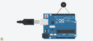
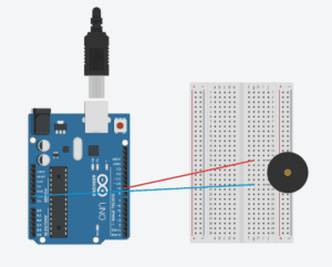
The circuit, on the other hand, is rather simple. As is shown in the program, i take port 3 as OUTPUT and GND as ground, and the whole circuit only consist of that two wire. The schemata is as follows.

Recitation 8 : Serial Communication – Lillie Yao

Exercise 1:

In this exercise, we had to make an Etch A Sketch with two potentiometers on the breadboard. We then had to connect Arduino and Processing so that they could speak to each other and tell one another what to do. For example, I stored arrays in Processing and then write a code in Arduino to communicate with each other.

This exercise was pretty straightforward but there was one part that really stumped me in the beginning was how to tell Processing to read and run the arrays through Arduino. I figured out that in order for sensorValues to run in Processing, I would have to embed it into the eclipse code as sensorValues[0] and sensorValues[1]. After running the code with sensorValues in both Arduino and Processing, my code was able to work.

After, we were told to make the circle into a line instead, to show a real Etch A Sketch. In this case, I just made added the command previousSensorValues so that the code would just keep repeating and repeating on top of each other, making a line continuous.

Circuit Schematic:

Documentation:

Circle

Line: Etch A Sketch

Exercise 2:

For this exercise, we were asked to create an instrument with a speaker using Arduino and Processing. I started out by making a separate tab for pitches, then I coded in Processing for mouse pressed. This exercise was also pretty challenging because I didn’t know how to tell Arduino to make the speaker sound. But in the end, I figured out that I needed to use tone and pin to tell Arduino and Processing to work together and make a sound. Making the circuit schematic was really fun and easy, but the exercise itself was pretty challenging for the sole reason because I didn’t know how to tell Arduino and Processing to communicate with each other.

Circuit Schematic:

Documentation:

Code:

Arduino-

#define NUM_OF_VALUES 2 /** YOU MUST CHANGE THIS ACCORDING TO YOUR PROJECT **/

#include “pitches.h”

// notes in the melody:
int melody[] = {
NOTE_C4, NOTE_G3, NOTE_G3, NOTE_A3, NOTE_G3, 0, NOTE_B3, NOTE_C4
};

// note durations: 4 = quarter note, 8 = eighth note, etc.:
int noteDurations[] = {
4, 4, 4, 4, 4, 4, 4, 4
};

/** DO NOT REMOVE THESE **/
int tempValue = 0;
int valueIndex = 0;

/* This is the array of values storing the data from Processing. */
int values[NUM_OF_VALUES];

void setup() {
Serial.begin(9600);
pinMode(8, OUTPUT);
}

void loop() {
getSerialData();

if (values[0] == 1) {
tone(8, values[1]);
} else {
noTone(8);
}

}

//recieve serial data from Processing
void getSerialData() {
if (Serial.available()) {
char c = Serial.read();
//switch – case checks the value of the variable in the switch function
//in this case, the char c, then runs one of the cases that fit the value of the variable
//for more information, visit the reference page: https://www.arduino.cc/en/Reference/SwitchCase
switch (c) {
//if the char c from Processing is a number between 0 and 9
case ‘0’…’9′:
//save the value of char c to tempValue
//but simultaneously rearrange the existing values saved in tempValue
//for the digits received through char c to remain coherent
//if this does not make sense and would like to know more, send an email to me!
tempValue = tempValue * 10 + c – ‘0’;
break;
//if the char c from Processing is a comma
//indicating that the following values of char c is for the next element in the values array
case ‘,’:
values[valueIndex] = tempValue;
//reset tempValue value
tempValue = 0;
//increment valuesIndex by 1
valueIndex++;
break;
//if the char c from Processing is character ‘n’
//which signals that it is the end of data
case ‘n’:
//save the tempValue
//this will b the last element in the values array
values[valueIndex] = tempValue;
//reset tempValue and valueIndex values
//to clear out the values array for the next round of readings from Processing
tempValue = 0;
valueIndex = 0;
break;
//if the char c from Processing is character ‘e’
//it is signalling for the Arduino to send Processing the elements saved in the values array
//this case is triggered and processed by the echoSerialData function in the Processing sketch
case ‘e’: // to echo
for (int i = 0; i < NUM_OF_VALUES; i++) {
Serial.print(values[i]);
if (i < NUM_OF_VALUES – 1) {
Serial.print(‘,’);
}
else {
Serial.println();
}
}
break;
}
}
}

Processing:

import processing.serial.*;

int NUM_OF_VALUES = 2; /** YOU MUST CHANGE THIS ACCORDING TO YOUR PROJECT **/

Serial myPort;
String myString;

// This is the array of values you might want to send to Arduino.
int values[] = new int[NUM_OF_VALUES];

void setup() {
size(500, 500);
background(0);

printArray(Serial.list());
myPort = new Serial(this, Serial.list()[ 2 ], 9600);
// check the list of the ports,
// find the port “/dev/cu.usbmodem—-” or “/dev/tty.usbmodem—-”
// and replace PORT_INDEX above with the index of the port

myPort.clear();
// Throw out the first reading,
// in case we started reading in the middle of a string from the sender.
myString = myPort.readStringUntil( 10 ); // 10 = ‘\n’ Linefeed in ASCII
myString = null;
}

void draw() {
background(random(0,255));

// changes the values
// for (int i=0; i<values.length; i++) {
// values[i] = i; /** Feel free to change this!! **/
//}

if (mousePressed){
values[0] = 1;
} else {
values[0]= 0;
}

values [1] = mouseX;

// sends the values to Arduino.
sendSerialData();

// This causess the communication to become slow and unstable.
// You might want to comment this out when everything is ready.
// The parameter 200 is the frequency of echoing.
// The higher this number, the slower the program will be
// but the higher this number, the more stable it will be.
echoSerialData(200);
}

void sendSerialData() {
String data = “”;
for (int i=0; i<values.length; i++) {
data += values[i];
//if i is less than the index number of the last element in the values array
if (i < values.length-1) {
data += “,”; // add splitter character “,” between each values element
}
//if it is the last element in the values array
else {
data += “n”; // add the end of data character “n”
}
}
//write to Arduino
myPort.write(data);
}

void echoSerialData(int frequency) {
//write character ‘e’ at the given frequency
//to request Arduino to send back the values array
if (frameCount % frequency == 0) myPort.write(‘e’);

String incomingBytes = “”;
while (myPort.available() > 0) {
//add on all the characters received from the Arduino to the incomingBytes string
incomingBytes += char(myPort.read());
}
//print what Arduino sent back to Processing
print( incomingBytes );
}