Recitation 9: Media Controller – Audrey Samuel

During this week’s recitation we were required to control an image or video by manipulating that media’s attributes using a physical controller made with Arduino. I decided to choose my image from Creativity103.com which was given to use in the resource file. I chose a “Christmas Light” image and decided I would use the Filter example, specifically using the “blur” function. On my Arduino board, I used a Potentiometer to manipulate the “blurriness” of the picture I had chosen. 

I began by opening the provided Serial Communication example code given to us. I used the Serial One Value codes as I was only sending a single value.  I then opened up the “filter blur” example and typed in the code onto the ‘one value from AtoP processing’ code. I then went onto the Arduino Serial One Value code and included the map function to transmit my Potentiometer values from Arduino to Processing. To do this, I included an int value: int picture = map(sensorValue, 0, 1023, 0, 300). I then made sure I included ‘picture’ in the Serial.write code. On my Processing code, I had to include PImage and under void setup() I loaded the photo I had used which I named “colors.jpg.”. I wanted to control the range of blurriness depending on which values my Potentiometer was projecting so I included an If statement under void draw() which stated that if(valueFromArduino > 150) then it would filter(BLUR, 2); but if(valueFromArduino <100 then it would filter(BLUR, 5).  Find below video. 

Christmas lighting effect

Reading

The article Computer Vision for Artists and Designers draws light to the importance of computer vision through vision-based detection and tracking techniques to show how computer vision can be used in society to benefit its people. Most people assume “computer vision” has no greater aim or purpose and cannot really do anything that will contribute to the betterment of individuals in society, however this article proves this assumption wrong. One of the examples provided that I found was a really smart way to incorporate technology was Rafael Lozano­Hemmer’s installation: Standards and Double Standards (2004). This installation consisted of fifty leather belts which were suspended at waist height with the help of servo-motors located on the ceiling. Through computer vision tracking system, the belts would turn towards an individual depending on their movement. This project metaphorically illustrates the power of the patriarchy in an artistic manner. This had me thinking about how we could use Arduino and Processing to distort/illustrate images to reveal a deeper meaning and convey a deeper message to society. Art through computer vision is an interactive and engaging way to capture the attention of the public and allow them to see the pressing issues faced within society that need to be addressed. 

Resources:
Computer Vision for Artist and Designers

Recitation 9: Media Controller by Alexander Cleveland

Introduction

In recitation 9, the goal was to create a processing sketch alongside Arduino code and have a physical tool on the breadboard which manipulates that sketch in some way. In this recitation, my goal was to use the core concepts of tinting we learned from class and tint an image. I didn’t want to use an image from the examples in class, so I used an image of my favorite building in Hong Kong, the Bank of China building designed by famed architect I.M. Pei. In this recitation, I used one potentiometer to control the values 0-1023 on a picture. With these values, I manipulated the picture of the Bank of China building to be tinted either blue or green, depending on which values the potentiometer was turned to. Although my project is minuscule compared to those in Computer Vision for Artists and Designers: Pedagogic Tools and Techniques for Novice Programmers, the interactive models inspired my method for tinting the picture. In the beginning, I thought it would be fine to just use a push button and correlate that with tinted values. But this fared far too simple as I wanted to push it just a little bit further. So, using Rafael Lozano-Hemmer’s Standards and Double Standards for inspiration, I used a potentiometer instead.

Building and Implementation

In order to initiate the coding sequence, I used one value from Arduino to Processing examples from class. These two templates gave me a base to write the rest of my code. In Arduino, I used Serial.write(sensor1) because I needed to translate these values from Arduino to processing since I would be controlling the tint with my potentiometer. After this, I mapped the possible values for a potentiometer (sensor1) (0-1023). Then I used serial.write(a) again to then translate these values into processing. All Arduino code can be viewed at the bottom of my sketch under “my code”

In the processing side of things, I needed to incorporate a few more parts to get the project up and running. I inserted the image “HK.jpeg” under a loadImage name. I did this also by defining PImage = img at the top of my code. After loading the image in, I fit it to the screen by using an if statement under void draw. This ensured that it was all visually pleasing before trying to tint it. Then I had to use the array given in the tint example in order to insert my port [16]. For this next step of tinting the image, I first defined sensor1 as (int sensor1) at the top of my code so that the Arduino code and processing code could interact. I also defined valueFromArduino which printed out the value from Arduino into processing. I then created an if statement saying that if valueFromArduino was greater than 150 on a scale of 255, then the picture would turn blue. I also correlated this with an “else if” that said if the potentiometer value is less than 149, then the image will turn green. Below both of these statements, I placed the tint function (red or green) colors. Below is a video of the completed project. 

In the beginning I was trying to use pixelation and pointillism, but realized it would not be possible to abide by the original rules of the recitation. When I switched to just a classic tint, everything worked out as planned. In the future, I might possibly employ the use of two different potentiometers to correlate with two different tinted colors.

My Code

Arduino

int a;
void setup() {
  Serial.begin(9600);
}


void loop() {
  int sensor1 = analogRead(A0);
  Serial.write(sensor1);
  int a = map(sensor1, 0, 1023, 0 , 255);
  Serial.write(a);
//  Serial.print(sensor1);
//  Serial.println();
  

  // too fast communication might cause some latency in Processing
  // this delay resolves the issue.
  delay(10);
}

Processing

import processing.serial.*;
PImage img;
Serial myPort;
int valueFromArduino;
int sensor1;


void setup() {
  size(600, 600);
  img = loadImage("HK.jpeg");
  imageMode(CENTER);
  background(255);
  
  printArray(Serial.list());
  myPort = new Serial(this, Serial.list()[16], 9600);
}

void draw() {
  if (img.width > 0) {
    image(img, 300, 300, width, height);
    //float a = map(sensor1, 0, 1023, 0, 600); 
    
    while ( myPort.available() > 0) {
    valueFromArduino = myPort.read();
  }
  println(valueFromArduino);//This prints out the values from Arduino
}
  
  if ( valueFromArduino > 150) { 
    tint(0, 0, 255, 150);
    image(img, 250, 0);
  }
 else if (valueFromArduino < 149) {
  tint(0, 255, 0);
 }
  }

Sources

Computer Vision for Artists and Designers: Pedagogic Tools and Techniques for Novice Programmers by FLONG.

Recitation 9: Media Controller by Yiwen Hu

In this recitation I applied what we’ve learned in class, the “tint” function which can change the background color of the video. I decided to use the potentiometer to change one value of the RGB.

Step 1: Insert the video. 

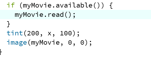
As we’ve learned in class, in setup() I wrote myMovie function and access it to the video file. I put the video file in the same folder as the processing’s, but under another folder called “data.” Then in void draw(), I wrote like this:

The tint appears after the myMovie read() if statement. And the image function is to make it appear in the sketch. As for the x, it’s the variable I created to change the color. The x will vary based on the potentiometer value.

Step 2: Let Arduino communicate with Processing 

For this step I refer to the example code in previous class. There’s not many change to it except the number of value and port number. For the processing, I put a setupSerial() in void setup() and updateSerial() in void draw(), which are defined in the following code. Another thing I create is the map function that translate the value of the potentiometer to the x, whose range should be under 255. 

After building the circuits, I run the code and it worked!

Essay: Final Project (Rodrigo Reyes)

The Better Reader 

The Better Reader is a project to help people with dyslexia or people with reading issues be able to read with more agility and accuracy. It will draw its inspiration from dyslexia reading exercises and the game of Wack-A-Mole.

The project’s foundation will be to develop interaction between the computer (using Arduino and Processing), and the human user. First of all, it will have communication between two languages in the computer world, which are Arduino and Processing. These two together will be interacting together to create animation,  audio, text, and sound depending on the human’s response to the computer. The interaction that we will design is supposed to be easy for the users to figure out. This last will be explained in the following paragraph.

The Better Reader will draw upon common exercises that are used to improve eyesight, as well as exercises for reading more quickly, and will combine this with the concept of the Wack-A-Mole game. These exercises which we draw upon have also been proven useful for people with dyslexia. A user will see on the computer (Processing will be used for the animation) three columns of three words each (nine words in total). One word is going to blink (disappear and appear) from the top left one by one and row by row until it reaches the last word and it goes back to the top to start again. This will allow the user to direct his attention to the word that is blinking, facilitating the interaction between humans and machines. The program will randomly stop at any given word and it will ask the user to identify the last word that disappeared and appeared. It will give for options (four words), and if you select the correct word, the program will accelerate the word blinking pattern to make it harder for the user to follow along. The user will have three “lives” (opportunities to lose and keep playing). To make it more engaging we will use Arduino to connect to a console that has four electronic buttons. These electronic buttons will have the word options written on them. This means that we will have to program the buttons to give different four-word options on each level, and it will obviously have to include the right choice in one of the buttons. The user will have a time limit to choose the right answer; we are thinking of limiting this time to five seconds. We want to have a hammer similar to the one in the Whack-A-Mole game so that the users can quickly hit the given answer.  Furthermore, we would like to have a scoreboard with the ranking of the people that have “played” this game in hopes of incentivizing friendly competition.

This exercise should be useful as it would allow users to develop their peripheral view, their concentration, and their short term memory.  It is not going to feel like those tedious exercises that we who have dyslexia have to do but is rather going to feel like we are just playing a game.  I think that understanding the struggle of dyslexia will push our team to focus on creating not just an exercise for reading but a game that is fun. Something that can put learning and fun together. Hopefully, there will be much to gain not just for people with dyslexia but for everyone.