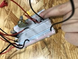
Interaction Lab-Recitation 1 (Ning Zhou)

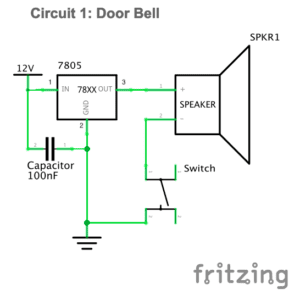
Circuit 1: Door Bell

Components:

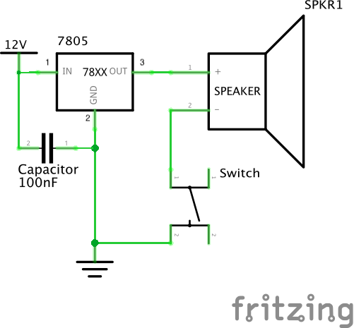
1*Buzzer: Creates sound with electric current flow. 

1*100 nF Capacitor: Stores electric charge.

1*Switch: Builds or breaks the connection in the electric circuit.

1*LM7805 Voltage regulator: Transfers the voltage level. Used to transfer 12V into 5V in our circuit.

1*12volt power supply: Provides 12volt power for our circuit.

1*Breadboard: A base board for us to build the model of electric circuit.

Several jumper cables: Build connection between components in the circuit.

1*Barrel jack: Connect the power supply and the circuit.

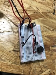
diagram

video:

Process: 

My partner Amily and I both knew little about building an electric circuit. So, we just followed the given diagram of the circuit and the instructions of the components at first. The speaker didn’t make any sound when I pressed the switch. Then we asked Jingyi for help. It turned out that we made several mistakes. One of the problems is that we set the ground and power wrong at the beginning, which is a big problem because many components need to be connected to the ground. Also, the directions of the current flow in the breadboard are different for the parts in the middle and the other parts on two sides. Another thing is that the switch with four legs is self-connected between the two diagonal legs, not the parallel legs. After figuring out these, we rebuilt the circuit and it worked this time.

Circuit 2: Lamp

Components:

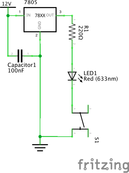
1*220ohm Resistor: Provides resistance and opposes the flow of electricity.

1*LED: Emits light with electric current flow.

1*Multimeter (missed): Used to measure resistance.

1*LM7805 voltage regulator,1*switch,1*100 nF capacitor,1*12volt power supply, several jumper cables,1*barrel jack,1*breadboard.

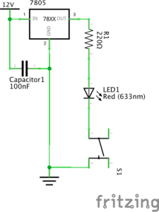
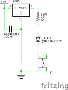
diagram:
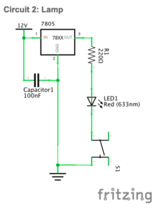
video:

Process:

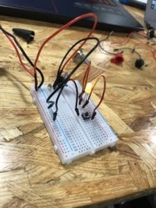
After the practice of the first circuit, Amily and I were clearer about each component’s function and how to connect them in the circuit. One thing we missed is that we forgot to connect the multimeter because we just focused on the diagram of the circuit in which the multimeter is not shown. We were not aware of this until we turned it in at the end of the recitation. But the circuit still worked well.

Circuit 3: Dimmable Lamp

Components:

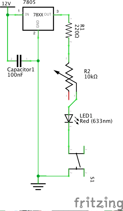
1*10K ohm Variable Resistor (Potentiometer): Provides variable resistance to oppose the flow of electricity. It can change the brightness of the LED in the circuit.

1*Breadboard,1*220ohm resistor,1*LM7805 voltage regulator,1* switch,1*LED,1*100 nF capacitor,1*12volt power supply,1* barrel jack, several jumper cables,1*multimeter (missed).

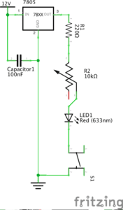
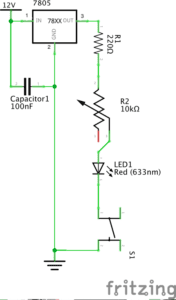
diagram:

video:

Process:

The circuit is similar to the second circuit so we built this one quickly. It didn’t work at first. We then found that there was a small problem of the connection of variable resistor. The middle branch should connect to resistor. We fixed this and made the circuit work. The brightness of the light changed accordingly when we rotated the variable resistor. We forgot the second task of switch the switches. Both of us missed the instructions for this part and simply thought that we only had the task of building the three circuits. To replace the push button, we can just take it off and leave the jumper cables as the same. Each jumper cables of the arcade button should be set in the same row as one of the other jumper cables left on the breadboard in order to allow the current flow.

Soldering task:

Reflection: My partner and I encountered many problems in our first recitation. We also missed some steps for our tasks. But after this recitation, both of us became more familiar with different components and the structure of circuits. More importantly, I learnt the lesson of doing preparation before class and paying more attention to the materials and instructions. Also, the sense of achievement that a successful circuit gives is awesome.

Question1:

After reading The Art of Interactive Design, in what way do you think that the circuits you built today include interactivity? Please explain your answer.

I think that the circuits we built include interactivity because they reacted to our actions. But I do not consider the action between the circuits and us as interaction. Similar to the refrigerator situation, when I press the button, they listened (to the pressed button), thought (with electric current through the circuits), and spoke (by creating sounds or emitting lights). These are the input, process, and output. The third circuit seemed to be more interactive than the other two because it can react to different actions accordingly. However, in all of the simple interactivity, we design the other actor so that we can predict their exact response. They are not actually thinking. What they do is mechanical process that built by us.

Question 2:

How can Interaction Design and Physical Computing be used to create Interactive Art? You can reference Zack Lieberman’s video or any other artist that you know.

In my opinion, interaction design and physical computing are both of great importance in interactive art. Interaction design is more like an inspiration while the physical computing is the process that transforms the theory into reality. Zach said that art is a form of research. I think that only during the process of conducting research could people find problems and then to create something new to solve the problems. In his third interactive art, Zack Lieberman together with other artists sought to create a new form for disabled graffiti artist to draw again. This is something that inspired them. Later by physical computing, they made their idea come true, and also made Tony’s come true. Being paralyzed could be considered as being largely disconnected to the outside world. The eye-writer enables Tony to build interactions again. One of my friends likes graffiti as well. Once I went out with him, watching him drawing on the wall. I felt like for them, the meaning of drawing is much about tagging, showing, sending messages and interacting with others with their drawings. So, I think that these values were acknowledged by Zach’s team and inspired their design.
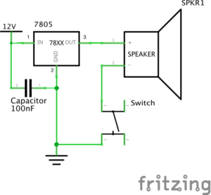
Interaction Lab-Recitation 1 (Serene Fan)

Circuit 1-Door Bell

Components:

1*Breadboard:  A base for connecting components

1*LM7805 Voltage Regulator:  To regulate and maintain a constant voltage level which is suitable for the circuit

1*Push-Button Switch: Able to connect the whole circuit when it is pressed

1*Buzzer: To output an audio signal

1*100 nF (0.1uF) Capacitor: To store electrical energy

1*12 volt power supply: To provide power source

1*Barrel Jack: An electrical connector for supplying direct current

Jumper Cables (Hook-up Wires): To connect components

The Diagram

The Building Process and Problems We met

How to connect the switch???  

When we were connecting the switch, we found it difficult to distinguish which two feet to choose. We expected there should be different length of the feet so that we could identify the anode and the cathode, but all the four feet seemed the same. Out of ideas, we turned to Nick for help. He then told us the way of connecting the switch was to  know that foot A and D are always connected. Same with foot B and C. Therefore, only connecting either A or D to either B or C can be counted as successful connecting.

Where is the voltage regulator???

We first built the circuit without the voltage regulator, because we misinterpret the symbol for the voltage regulator as the power source. Since the circuit still worked well, we did not notice this mistake. However, Leon came by and pointed out that we should add the voltage regulator to the circuit in case the voltage level could be too high for it. Therefore, we corrected our circuit and it worked again. 

Circuit 2-Lamp

Components: 

1*Breadboard:  A base for connecting components

1*LM7805 Voltage Regulator:  To regulate and maintain a constant voltage level which is suitable for the circuit

1*Push-Button Switch: Able to connect the whole circuit when it is pressed

1* Arcade Button: Able to connect the whole circuit when it is pressed, but needed to be soldered

1*220 ohm Resistor: To reduce current flow

1*LED: Able to emit light when connected to the power source

1*100 nF (0.1uF) Capacitor: To store electrical energy

1*12 volt power supply: To provide power source

1*Barrel Jack: An electrical connector for supplying direct current

Jumper Cables (Hook-up Wires): To connect components

1*Multimeter: To measure voltage, current and resistance

The Diagram:

The Building Process and Problems We met

Why the light was not on???

We built the circuit exactly as what the diagram told us, however, the LED just refused to emit light. We checked every connecting point without recognizing any problem. At last, we asked Nick about this situation. As he suggested, we used the multimeter to measure the resistance and surprisingly figured out that we connected the wrong resistor, which was only 10 Ω. We immediately altered the resistor and the light went on.

We replaced the switch!

After soldering the arcade button, we decided to replace the push-button switch. The process was quite simple. And we found that there was no need to take down the push-button switch while connecting the arcade button.

Circuit 3-Dimmable Lamp

Components

1*Breadboard:  A base for connecting components

1*LM7805 Voltage Regulator:  To regulate and maintain a constant voltage level which is suitable for the circuit

1*Push-Button Switch: Able to connect the whole circuit when it is pressed

1*220 ohm Resistor: To reduce current flow

1*10K ohm Variable Resistor (Potentiometer): To change the resistance in a close circuit

1*LED: Able to emit light when connected to the power source

1*100 nF (0.1uF) Capacitor: To store electrical energy

1*12 volt power supply: To provide power source

1*Barrel Jack: An electrical connector for supplying direct current

Jumper Cables (Hook-up Wires): To connect components

1*Multimeter: To measure voltage, current and resistance

The Diagram

The Building Process and Problems We met

Why the light was not on again???

Again, we followed the diagram but found the light was not on in a close circuit. Based on experience, we checked the resistor and were sure it was the right one. What confused us was that the first time we pressed the button, the light was on perfectly. However, every time we pressed the button, the light became dimmer until it vanished completely. We were afraid that we might have burnt the light for some unknown reason, so we asked Marcella for help. She checked our circuit and told us we connected the variable resistor in a wrong way. 

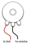
As the picture above shows, we then connected the left and the middle terminals into the circuits. It turned out that the circuit worked well and we did not burn the LED.

Reflection

The diagrams were simple enough to understand and the building process was quite easy. However, we still met problems. After the solutions were figured out, I reflected on why these problems have come up. One reason was that we did not read the instructions carefully enough to clearly know how to connect every components. Another reason was that we were not familiar with the breadboard, which made us panic easily every time there existed problems. For solutions, I found a helpful piece of reading in the instructions for this recitation called “Getting Started in Electronics”, through which I could access detailed basic knowledge of electronics. 

Answers to the questions

Question 1:

After reading The Art of Interactive Design, do you think that the circuits you built today include interactivity? Please explain your answer.

According to The Art of Interactive Design, there is no absolute answer to the question of whether an object is interactive. Instead, the degree of interactivity varies subjectively. Therefore, the circuits I built in the recitation can be regarded as interactive. As the author defines, interactivity happens when actors listen, think and speak, which can also be defined academically as input, process and output (5). In this case, one actor is the circuit while the other is the person who presses the button. During the process of interaction, the circuit listens (to the action of pressing the button), thinks (through processing the action), and speaks (by turning on the light or the speaker). Therefore, there did exist interaction.

Question 2:

How can Interaction Design and Physical Computing be used to create Interactive Art? You can reference Zack Lieberman’s video or any other artist that you know .

Interaction Design functions as a mediate for its objects to create Art, and Physical Computing can be used as a tool to achieve Interaction Design. In Zack Lieberman’s video, he launched three artistic practices, respectively called “Drawn”, “iq Font” and ” Eye-writer”, with his software skill. Through these practices, his softwares allow people to create Art and expresses with low barrier. That is how Interaction Design and Physical Computing can be combined to create Interactive Art.

Int Lab Recitation 1 Documentation by Daniel Chin

Writer: Daniel Chin 
Recitation partner: Linhui 
 
This is a write up for Interaction Lab SP18 Recitation on Electronics and Soldering on Feb 15, 2019. 

Components: what are they? 


Breadboard 

A pre-organized cable layout, easy to plug in jumper cables and other units’ legs. Good for organizing circuit. Good for when you want to start building a circuit but your mind is a blank. 

LM7805 Voltage Regulator 

Turns 12V DC to 5V DC. This, with the power supply, gives our buzzer and LED a friendly 5V. 

Buzzer 

Add direct current and it plays a 2200 Hz pitch. In our circuit, it is the output. It signals the user that the button is pressed. 

Push-Button Switch 

Use a finger to tell it whether to let current pass. 

Arcade Button 

A cooler Push-Button Switch. Acts as the input in our interactive circuit. 

220 ohm Resistor 

Add resistance. In our circuit, it alleviates some voltage off our LED, so that the LED won’t pop. 

LED 

Consumes electricity and emits red light. Very picky about which way the current goes. In our circuit, it is the output. 

100 nF (0.1uF) Capacitor 

To let the Voltage Regulator work. 

10K ohm Variable Resistor (Potentiometer) 

A resistor whose resistance we can control by rotating a disk. In our circuit, it controls the brightness of the LED. 

12 volt power supply 

Turns 220V AC to 12V DC. Today we plugged it into the wall and we have a safe voltage to play with. 

Barrel Jack 

The cable of the power supply doesn’t go into the breadboard. The barrel jack solves the problem. 

Multimeter 

Measures U, I, and R. We used it to find the right resistor. Also, as documented below, we used it to check for short circuit. 

Several Jumper Cables (Hook-up Wires) 

Cables that are easy to use with the breadboard. Makes building circuits as easy as drawing lines. 
 

The circuits 


Scheme of buzzer ↓ 
scheme of circuit 
 
buzzer working ↓ 


Scheme of LED ↓ 
scheme of circuit 
 
LED working ↓ 
 
 
Scheme of dimmable LED ↓ 
scheme of circuit 
 
Dimmable LED working ↓ 


Problems and how we solved them 


We encountered several problems during the recitation. 

1. Voltage regulator: which leg is which? 

We found the spec in recitation instruction webpage. 
 

2. Push-Button Switch: Four legs??? We only need two 

We asked Tristan. Problem solved. 
“Imagine they are claws.” Each claw has two fingers. The fingers of the same claw are connected. The button controls the connectivity between the two claws. 
 

3. Untitled 

Before plugging in, we checked for short-circuit with the multimeter on last time. 
It seemed to short! (The overall resistance of the circuit was 0) 
We checked the circuit and the current flow, and solved the problem. 
 

4. Untitled 

When final double checking, we found we missed a cable (from regulator IN to 12V). 
We added the cable. 
 

5. Oh no, we still got the legs wrong 

Circuit plugged in for 10 sec, Linhui reports abnormal smell. 
We detached power immediately. I found the voltage regulator very hot. 
We asked Leon. It turned out we got the voltage regulator spec perspective direction wrong. 
“Think about it as a chair. This is the back side of the chair.” 
We rotated the voltage regulator 180 degrees. Finally, the circuit worked as expected. 
 

Questions and my answers 


After reading The Art of Interactive Design, in what way do you think that the circuits you built today include interactivity? Please explain your answer. 

I think the circuits we built today provide feedback, but no interactivity is provided as is defined by The Art of Interactive Design. What we built are simple circuits, and are less interactive than the fridge example mentioned in the article. Here is why I think that. As defined in the article, interaction is the repeated process of “listen, think, speak” between two “actors”. In the fridge example, the “thinking” is simple, but the “speaking” is richer than the doorbell and LED we made today: When the fridge light powers on, the user sees the contents in the fridge, and that information input is way more dynamic and engaging than a simple LED. 
 

How can Interaction Design and Physical Computing be used to create Interactive Art? You can reference Zack Lieberman’s video or any other artist that you know. 

I personally believe that even a piece of writing, if good, can be interactive. Through carefully designed words, the writer can make the reader read, think, and respond to the text. Of course, the writing “thinks” too, and responds to the reader through the pre-determined but unpredictable chapters/paragraphs. 
 
The multi-model communication that Physical Computing offers only assist the good writing. Certainly, the power of real-time computing makes non-predetermined response possible, but any system, no matter how dynamic, requires “playwriting” or “designing” before the user steps into the picture. I think the quality of this playwriting is critical. 
 
For example, the game Undertale is highly praised for its integration of its relationship/emotion system and its combat system, but what I find interesting about Undertale is its character speeches. They are very smartly designed. It is good writing. Without good writing, assistive technology like an interactive gaming environment can never make an experience truly engaging. 
 
In conclusion, I think Interaction Design and Physical Computing are tools that open more options for expressing and listening, but to make something interactive, good playwriting is at the core. In the end, the creation only speaks for the creator. If the creator does not have something interesting to say, the creation would at most be a fancy toy. 

Recitation 1 (Megan Rhoades)

Circuit 1: Door Bell

Parts: 

  • Breadboard: Provides a base for the connections in a circuit
  • LM7805 Voltage regulator: Controls voltage, allowing for consistent output
  • Switch: When pressed, connects the circuit to allow power to reach the speaker
  • Speaker: Vibrates, creating a sound, with the introduction of electric current
  • Jumper cables: Provide connections for the circuit
  • Barrel jack: Connects power supply to outlet
  • 100 nF (0.1uF) Capacitor: Stores (and helps regulate) electric energy
  • 12 Volt Power Supply: Provides power source

Process:

  • While this was the simplest circuit, we had to acclimate to using the components and building circuits. The biggest challenge for us in this aspect was figuring out the difference between the power and the ground, especially when connecting the voltage regulator. Finishing the circuit also provided some difficulty, as we were initially unsure of how power was flowing to the ground from the buzzer and switch. Moving on in the class, I know that I will have to put more effort into distinguishing which wires should be ground. Despite this confusion, we finished this circuit fairly quickly after getting used to the components. 

Circuit 2: Lamp

Parts: 

  • 220 ohm Resistor: Reduces current flow
  • LED: Emits light with electric current
  • Multimeter: Used to measure resistance

Process:

  • The most difficult process in this circuit was learning to measure the resistor with the multimeter. Since our fingers effect the reading of the multimeter, we asked for advice and found that measuring the resistor in between our fingers gave an accurate reading. After finding the correct resistor we simply made small adjustments to our previous circuit in order to add the LED and the resistor.

Circuit 3: Dimmable Lamp

Parts:

  • 10K ohm Variable Resistor (Potentiometer): Allows for interaction, with a turn of the dial adjusting the strength of the electric current

Process:

  • This circuit was the easiest of the three. After adjusting the position of the light, we simply added the variable resistor. I did feel that I learned something from observing the interactivity of the resistor — this technology is basic yet I had never put thought into how it works. For that reason, this circuit was the most interesting to us. 

Push-Button Switch

Process:

  • After finishing circuit 3, my partner and I disassembled our circuit. For this reason, we had to reassemble the circuit for the inclusion of the new button. We had some difficulty with this new circuit. Again, we found ourselves confused with the difference between ground and power. We also found ourselves debating ways in which we could cut down on the number of jumper cables, simplifying our circuit. Although we had some difficulty we did eventually create a new circuit and I found the process useful in practicing the building process.

Question One

The interactivity reading introduced the idea that interactivity comes on a spectrum. This felt very clear to me thinking on the different circuits we built in recitation. The third circuit, which included a dimmable light, felt more interactive than those which had only a switch. Although all required action from a human (the press of the switch) to operate, this circuit was more responsive, giving not only the option of on/off but also the ability to control how much light was emitted. 

Question Two

As someone who is very interested in music, there are many interesting interactive possibilities. One idea that I have seen in an exhibit in my hometown in Ohio is an orchestra made of “electric instruments” — one example being a harp which sensed the movement of a human finger in a certain place and played the correct tone in response. I think this idea could be developed to help disabled musicians, similar to the EyeWriter being used to allow a disabled graffiti artist do his work. These examples which combine human creativity and electronic tools are especially interesting to me.  

Electric Circuits, Electrical Components and Interaction – Monika Yosifova Response

My experience in my first ever Interaction Lab Recitation was not what I expected. I didn’t know that there were so many people taking that class and it was truly exciting to actually get to meet new people. The girl that I was working with on the electric circuits project is called Tiana, and we both worked really hard to understand how both soldering and building circuits operated!

Circuit 1:

For the first circuit we used a Breadboard to help us organise our electric circuit. We connected this breadboard to a 12 V power cable which was the source of electricity for this circuit. We connected the red cable from that 12 V Power supply to the positive charged slots on the breadboard and the black cable we connected to the Negatively marked slots on the breadboard. This made everything that was connected to the Negatively charged slots ground. Then Tiana and I plugged in the Voltage regulator in the breadboard, it controlled the amount of power output throughout the breadboard. We connected sections 1 and 2 of the Voltage regulator together with a 100 nF Capacitor which condensed and stored some of the energy throughout the circuit. I then used a black cable to connect section 2 of the voltage generator to ground. Managing to get the Switch Button to work was more difficult as we had to watch the placement for it more carefully. We made a few mistakes with it’s placement and needed help figuring it out. Lastly, we put in the Speaker, plugging it in with energy from the 3rd slot of the Voltage Regulator. When we pressed the Switch Button after we plugged the circuit into the power, we heard a rather loud “WOOOM” sound and we celebrated.

Note: We originally hadn’t plugged the Voltage Regulator in and were wondering why it wasn’t working. We were being too careful with it cause we though we’d break it.

Circuit 2:

Circuit 2 personally gave me the most satisfaction to make. I love lights and as someone who never studied physics before, it was always amazing for me to see how people made a light turn on. When Tiana and I managed to get Circuit two done correctly, with no help, I felt like a Air-bender or a wizard (only for electricity). 

Similarly to circuit 1, our group utilized the Breadboard, the 12V power source, the Voltage Regulator and the capacitor  in a  way similiar to before. Section two of the Regulator was plugged into ground while section one was plugged into  power. The Capacitator was again used to connect Sections 1 and 2.  It got more interesting once Tiana and I had to figure out which resistor to use. We had been provided with two and had a difficult time finding out which one was the best. Professor Cossovich came over and explained the color-coding on the little resistor to us and we were good to go. This 220 Ω  resistor reduced the flow of electricity along the circuit and we connected it to one end of the little yellow LED light bulb that we were supposed to turn on.  Tiana then put in the Switch button, connecting one of the ends of it to ground while the other one was connected to the LED. Once we pressed the Switch, the little light turned on.

Circuit 3: 

Circuit three was by far the most complicated, but after being able to successfully make the previous two circuits, Tiana and I were really excited and just got on with the job. Class had already ended, but we were so curious about what the next little challenge was that we just wanted to construct it.

Similarly to the last two circuits, we utilized the Breadboard, the 12V power input, the Voltage regulator and the Capacitor, connecting Section two with the Capacitor to ground. Section 1 of the Voltage Regulator was connected to Power. Section three we connected to the 220 Ω Resistor again, with red cables, and then we connected it to section two of the Potentiometer. The potentiometer allowed for more control around the circuit as we connected its third section to the Led light. The LED light we then connected to the Switch Button again. There was a black cable that connected ground to the Switch on the other end. When we connected the circuit to the power, the LED automatically switched on, which was a mistake. Professor Cossovich then told us that we had, again, plugged in the Switch Button wrong.  After fixing that, the circuit worked!

Responding to Question 1:

I really had a laugh with some of my friends after reading “The Art of Interactive Design” article.  I though it was an engaging read. 

The circuits that we build in the Friday Recitation class were highly interactive as they created a level of concentration among the pairs that were building them. I had never worked with Tiana before, but the two of us were listening to each other, thinking about how to make the circuits work and communicating what we though was the correct way. It was a good project that brought me closer to someone I never honestly thought I’d work with, and I enjoyed it a lot! 

Responding to Question 2:

Interaction Design and Physical Computing be used to create Interactive Art in many ways. People get shocked and impressed by little things, an example for that would be the “Open Mouth” idea that Zach Lieberman explains to us when he presented his interactive music art to other people. Physical computing and Interaction design, if used correctly and coded properly can revolutionize art and expand people’s imagination and belief of the possible. I know it sounds cheesy, but I like to make people happy, and art that is produced in a way that the audience can interact with it always pleases people. 

Thank you for an awesome first week!

Monika V. Yosifova