Recitation 1: Electronics and Soldering By Tiana Lui

Author: Tiana Lui, Class: Interaction Lab, Professor Cossovich

2.15.19

Components of the circuits: what they do and why are they included

1 * Breadboard- this is where the circuit is connected by wires. The breadboard connects components of a circuit together. A completely connected circuit is necessary for the circuit to work.

1 * LM7805 Voltage Regulator- Voltage regulators maintain a constant voltage level. They are important because many electronic devices only work properly within a certain range of voltage, and voltage regulators can make sure the voltage supplied in the circuit stays within that optimal range.

1 * Buzzer- A buzzer is an electrical device that converts one type of power to audible sound. 

1 * Push-Button Switch- Switches are a control that can be used to interrupt the flow of current through a circuit. A pair of contacts within the switch are connected or disconnected depending on the physical position of the switch. When connected, the circuit is complete, and can execute tasks. When disconnected, the circuit is unattached, and the electronics do not execute anything.

1 * Arcade Button- Another type of switch.

1 * 220 ohm Resistor- A resistor is a two-terminal electrical component that resists the flow of electricity, and can be used to control the flow of current.
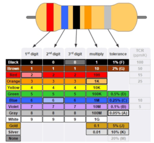
Resistors are marked with a series of colored stripes which indicate their amount of resistance.

1 * LED- Light-emitting diodes are a type of diode which can act as a visible or invisible light source. They are frequently used as indicator lamps in many electronic devices, or collectively as a display.

1 * 100 nF (0.1uF) Capacitor- Capacitors store electricity while current is flowing into them, then release the energy when the incoming current is removed. Capacitors can also be used to stabilize and smooth the flow of electricity.

1 * 10K ohm Variable Resistor (Potentiometer)- A resistor with the ability to change and control how much resistance to electrical current that programmer wants.

1 * 12 volt power supply- The power supply provides the power for the circuit to conduct electricity.

1 * Barrel Jack- Barrel jacks are electrical power connectors used for attaching extra-low voltage devices such as consumer electronics to external electricity. This is needed because we need a way to connect our circuit to power in order for there to be electricity/power to make the circuit run. 

1 * Multimeter- Multimeters can measure the current, voltage, and resistance of objects. They are useful for identifying the correct components with the correct current, voltage, and resistances to place into your circuit. 

Several Jumper Cables (Hook-up Wires)- Wires connect the circuit together. Without wires, electronic components are detached and the circuit is unable to work, because only a completely connected circuit will work.

Diagrams of the circuits

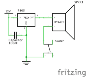
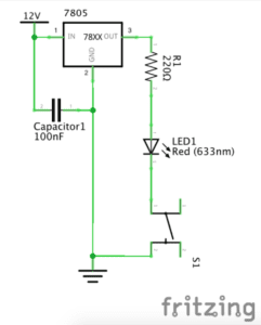
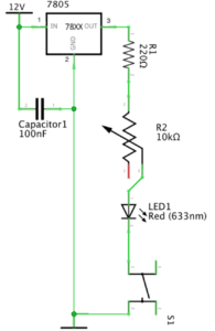
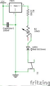
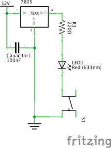
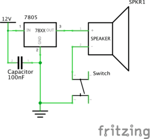
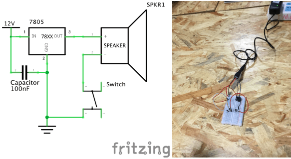
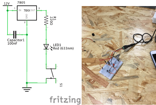
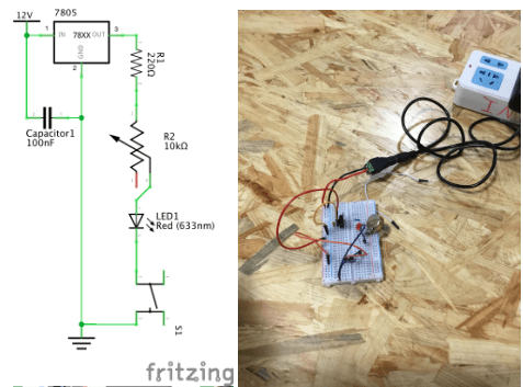
Below are the schematics of the circuits we built. The first one is a doorbell circuit, the second is a circuit of an led lamp, and the final circuit is a dimmable lamp circuit. 

doorbell

lamp

dimmable light

My notes

This was the first class we used the breadboard.

Initially, the breadboard was confusing to use, because we didn’t know what wires went where.

The picture of how the breadboard works helped us (the breadboard is composed of two strips of metal on the side and rows of metal on the inside).

We found out how to translate the circuit drawing to the breadboard.

So, to translate drawing to circuit, identify power source (12v this time).

Tip: keep power source wires on the side of breadboard (on the two vertical metal strips)

In this case, power source has two wires, one for power and one for ground

Continue connecting things to those immediately next to it in the drawing

If in the drawing, something is next to ground, connect component to ground on breadboard.

If in the drawing, something is adjacent to both power source and ground, connect component to both ground and power source.

Voltage regulator had a 3 pins, and the order in which it was connected to other components mattered. The way to distinguish the pins is to understand that the bulky part (package) was the front. Knowing this made it easy to identify the order of the pins that corresponded to the drawing.

Keep the capacitor close to the voltage regulator. For some reason, the circuit will work better this way. Why?

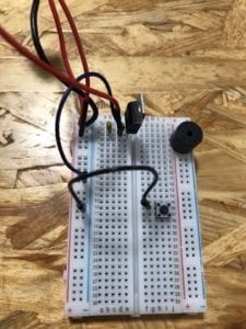
Make sure the buzzer is in line with your wires. The buzzer is bulky and bigger than the width of the pins you input, so make sure to check that you put your wires next to the pins.

Tip: keep the buzzer slightly tilted/not all the way in to double check the positionings of its pins so you can accurately place wires next to those pins

There are different ohm resistors. You can check their color codes or use the multimeter to measure their ohms. color codes for resistor
The multimeter reading didn’t work for us as the number kept jumping around. Need to understand how to properly get a multimeter reading. Also need to keep in mind conversions between units (ie. ohms and kiloohms)

The switch has an orientation. It should be placed horizontally, (longer side connects on same row)
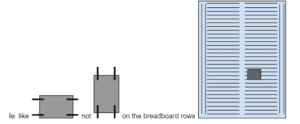
Picture of correct and incorrect orientation of switch on breadboard

Unplug the power source every time before you move wires around, otherwise components can get fried and damaged.

We were only able to complete 2 circuits. We didn’t test out the push button we soldered.

Soldering (pretty straightforward)

There’s a machine that controls the temp of pen and makes a pen super hot, a stand for your soldering pen which has a cleaning sponge to clean the pen, metal wire you melt onto the two things you want to connect, a wire stripper, wire cutter…

The pen thing just gets really hot so you can melt metal.

Always clean pen (stab it on the sponge) to preserve its longevity and prevent rust.

A good solder is even and connects the two places you want to connect

Strip a bit of the end of wire, connect it to other part, solder by melting wire with pen, the melted metal should touch both exposed wire and other part.

Don’t breathe in fumes, they are toxic

Aren’t we supposed to have masks and some sort of vent/fan that captures/draws away the toxins???

Other advice

Most times, if circuit is good, double check the position of your capacitor?

Pictures and Video Captures

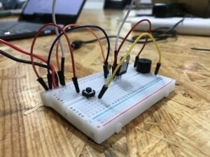
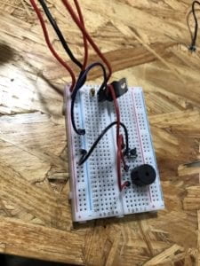
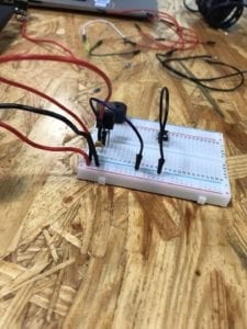
doorbell circuit completed doorbell circuit WIP doorbell circuit WIP

LED lamp circuit

Question 1:
After reading The Art of Interactive Design, in what way do you think that the circuits you built today include interactivity? Please explain your answer.

According to The Art of Interactive Design (Crawford), there are low and high levels of interaction. Since the circuits we built on Friday were relatively simple and only performed one task upon execution/under our influence, the circuits could be considered low-level interaction. However, the code and time required to build these circuits are much more complicating, and so our interaction with the circuits are relatively high and long. It is very challenging to define whether something is interactive or not, as there is no consensus on the scope of interaction. Does opening the refrigerator count as interaction, or does it count as talking to a brick wall? Does interaction only count when there is feedback both ways? And what type of feedback is qualified to be “interactive”? These are questions that need to be answered first before anything can be defined as interactive or not.

That said, the circuits we built on Friday, have various instances of interaction. For example, a human finger (analog input) pressing a button, causing the circuit to connect and complete. Or, the breadboard circuit communicating with the computer/arduino software, causing the electronics to execute actions. We also interacted with the hardware, placing wires into the breadboard, however, in that moment, the breadboard was not attached to the computer, hence, the breadboard gave no feedback, and may not count as interaction. We also interacted amongst ourselves, communicating with each other on how best to build the circuit. Above are examples of interaction, where two things that came in contact with one another produced some sort of action or communication.

Question 2:
How can Interaction Design and Physical Computing be used to create Interactive Art? You can reference Zack Lieberman’s video or any other artist that you know. 

Interaction is about two or more things connecting, and communicating something to each other or spurring some sort of action to be executed. Physical computing is great for interactive art because physical computing is about making an electronic device communicate with computer software to perform some sort of action, a process that is already interactive. Interactive art using physical computing is also scalable, in the sense that the programmer can start by programming a low-level interaction, then move on to coding more complex interactions, generating higher-level communication and engagement between the computer, user, and artwork.

Physical computing can be combined with any type of interest to form an interdisciplinary study, so it is not unusual that physical computing is combined with art. One such artist, Zach Lieberman uses interactive media to explore the relationships between technology, performance, and the body. He has created projects including an open-source eye-tracking system that allows disabled artists to draw using their eyes, and a performance that includes drawn sketches that react to a visitors’ touch. 

In summary, the world is your oyster. It is up to your imagination to use physical computing to create interactive art.
Recitation 1. Circuit Basics by Eva

Recitation 1: Electronics & Soldering

Instructor: Marcela

Partner: Ally

Materials)

  • Breadboard – a device for temporary prototyping electronics as the layout allows easy access for making connections and experimentation in the production stages.
  • LM7805 Voltage Regulator – to maintain voltage output – a regulator is incorporated for sustainability of the Volt current. In this case, it allowed the 12V DC to be at 5V DC which would not blow the LED.
  • Buzzer – the output signal once pressed (input). For our circuit prototyping, it allowed us to confirm that the circuit was functioning.
  • Push-Button Switch – (can be input or output) let the electricity flow through the circuit.
  • Arcade Button – an alternative input element to the push-button switch. Serves the same purpose, with a different design. 
  • 220 ohm Resistor – The resistance that maintained our LED intact. An additional obstacle for the voltage to pass.
  • LED – light-emitting diode, served as output when circuit was functioning. 
  • 100 nF (0.1uF) Capacitor – for the LM7805 Voltage Regulator to be functional. 
  • 10K ohm Variable Resistor (Potentiometer) – With this resistor we were able to control the current going to the LED, thus being able to dim it and brighten it.
  • 12 volt power supply – The 220V AC was translated to 12V DC which was a safe Voltage for us to prototype and experiment on. 
  • Barrel Jack – were able to connect the power supply to the Breadboard with the Barrel Jack, (much like a plug power converter).
  • Multimeter – although contains many more options, we used the Multimeter to detect the appropriate resistor (of 220 ohm).
  • Several Jumper Cables (Hook-up Wires) – flexible, easy to plug in wires that worked very well in Breadboard connections for our circuits. 

CIRCUTS 

  1. Buzzer

Although fairly simple, this circuit was crucial in my foundational understanding of Energy and Ground. We specifically made sure to use the red jumper cable to connect the electricity flow to the buzzer component – to visually emphasise the concept of ‘power’. In addition, the black jumper cables were emphasising the connection to the Ground.

2. LED

Although we were pretty lucky in managing to find the correct corresponding holes on the Breadboard in the first circuit, the second one rose some challenges. In this phase, it was reiterated that the ‘legs’ of the LED are very specifically classified – the longer wire corresponds to positive/power, and the shorted leg corresponds to negative/ground. After we figured this out, we were able to switch around the LED and get the electricity running though the circus, thus allowing the LED to light up. 

3.  Dimmable Light

In this phase, we added a Potentiometer to customise the brightness of the LED. Although I cannot speak about the first attempt (as it was not successful), we decided to build it from scratch again.  I think this was an important aspect, because once we realised we cannot track the bug/error, we chose to not waste time in rebuilding each part of the circuit separately. I now reflect that we were able to do this as it is a still fairly simple design, which got me wondering how I would tackle such an issue on a larger prototype. How the two attempt might have been different? In this stage, I realised it was crucial to understand the logistics behind all of the components, because as we gained a greater understanding of the hardware we were working with (by the help of the fellows), the logical layout of the design made sense (in my head) thus it was more manageable to replicate it physically.

QUESTIONS

1. While reading “The Art of Interactive Design” I was able to differentiate between the concept of “interaction” and “reaction” (“It takes two people to have a conversation, and it takes two actors to have an interaction”). When thinking about the circuits we constructed, I applied the concept of the Degrees of Interactivity to better comprehend what our end-goal was. For example, when thinking about the buzzer – a button is pressed, therefore a sound is outputted – which I would consider a low degree of interactivity. The user does not have a choice of input, and there is only one possible output. In comparison, the addition of the Potentiometer allowed the degree of interactivity to rise – the user now has a choice of where to turn the ‘pointer’, and thus the output varies also. I also began to think how else this degree might increase in my future creations – the instructions – THE CODE. By customising the settings (both possible input and  output) the degree of interactivity rises. This really sparked my curiosity of “what else I can make happen”, especially in relation to Art and Design!

2. I currently began exploring how Artificial Intelligence  is used for style transferring when creating Art  [current favourite digital artist Gene Kogan]. I have never associated art with computers before University, so to start realising how well they interlink when creating is very motivating for an aspiring artist in the Digital Age. This emerging technological era just shows how tools like Interaction Design or Physical Computing can be customised to flourish creativity. I realise the power you gain once you learn the native language, in this case ( the instructions  through ) CODE in relation to the hardware. All of these tools aid us, but cannot do for us, therefore learning to follow an idea from initial stages of development to an end-product requires, not only diligence, but fundamental understanding of the “so-called place” you are creating in or with (online / Breadboard / robotics / etc). For Art to be Interactive, the artist has to know their direction they want to take with their audience  and the Digital Age tools serve as an accessible source for exploration of own ideas. 

Recitation 1, Professor Young Chung, Zhenming Wang

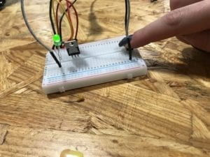
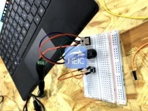
This is our first circuit–the doorbell circuit. It includes the power,  a capacitor of 100nf, a voltage regulator, the bell, the switch and the breadboard. First thing that confused a lot was the way to use the breadboard. It took us a while to figure out how to use it. After that, everything work well. 

This is our second circuit, the LED circuit. It includes capacitor, voltage regulator, a resistor of 220 oum, an LED and a switch. The process went on quite fluently. 

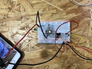
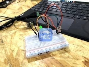
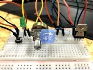
This is our third circuit, it includes one more variable resistor compare to the former circuit. At first, the circuit didn’t work well, however, we then found out that it was the problem of the switch and the variable resistor, we then try to adjust them. At last, the LED lighted, but the light was really slight. 

For the three circuits, they all include a capacitor,, and the usage of it is to store electrical power and then release it .It’s designed to add capacitance to a circuit. Besides, all of them include a voltage regulator, it’s used to adjust the voltage of the power to a voltage that is suitable for the appliances, since different electrical devices have different working voltage . For the variable resistor in circuit 3, it’s used to adjust the current flwing in the circuit in order to control the lightness of the LED.  

Answer to the questions:

  1. I think the interactivity is invovled in the process of building the circuit. One example is that when we finished building it, the electrical appliances worked. The door bell rang and the LED shines. That is a way that the ciircuits provide us with feedback, or interact with us.
  2. The answer is quite clear to the question. Through interaction design and physical computing we can create much more complicated circuits and we can make use of different kinds of sensors and mini computer to make the circuits interactive. That’s the charm of technology. 

Isaac Schlager Week 1 Recitation (Professor Eric Parren)


Recitation 1
Circuit 1: Doorbell

This circuit consisted of multiple elements, starting with a 12 volt power source at the beginning. Without this component, the circuit would have no power. The next component is a voltage regulator and its job is to maintain a consistent voltage level. There is also a capacitor that decreases the power level. The charges coming out of the capacitor and the second output of the regulator both get grounded, while the charge coming out of the third outlet goes directly to a speaker that makes noise and a switch that allows you to control whether noise comes out of the speaker or not. The purpose of this circuit is to emit noise out of a speaker. During the process of building the speaker we ran into a number of challenges that centered around our voltage capacitors being inefficient. We had to exchange three capacitors until our circuit was working properly.

Circuit 2: Lamp

Our second circuit and its purpose was to light a small LED light. It began with a 12 volt power source that entered into a voltage regulator that maintained a distinct voltage level, as well as a capacitor that lessened the power in the circuit.The charges coming from the capacitor and the second outlet of the regulator both get grounded, while the outward charge from the regulator travels through a resistor. This resistor does exactly what it is entitled and resists the current coming through it. Then the charge travels through the LED light that is supposed to light up and then goes through a switch that allows you to control the light manually.

Circuit 3: Dimmable Lamp

The third circuit we were required to built had to light up another LED light, but had to have the ability to turn a knob and dim the light. It began with a 12 volt power source that entered into a voltage regulator that maintained a distinct voltage level, as well as a capacitor that lessened the power in the circuit.The charges coming from the capacitor and the second outlet of the regulator both get grounded, while the outward charge from the regulator travels through a resistor. This resistor does exactly what it is entitled and resists the current coming through it. The charge then goes through a variable resistor that allows you to manually change the amount of resistance to the current before it enters the LED light and a switch.

Question 1: In a way, our circuits include interactivity because the different components in them communicate with one another. I believe they do this through the energy/ charge itself traveling through the circuit. It seems as though each component decides to either alter the charge or is altered by the charge before it is grounded. I also think the circuits are interactive in that they all have switches that we can interact with.

Question 2: I think that both Interactive Design and Physical Computing can be used to create Interactive Art in that the technology used can involve an audience. One of the examples that Zack Lieberman mentions is the “open mouth phenomenon”, where he feels that it is the pathway to someone’s heart. This can be influenced by Interactive Art that is created from Interactive Design and Physical Computing, an example being the car/ driver project that Lieberman works on. These projects involve a lot of research behind them in order to be constructed and many people do not realize that.

Documentation 1 – Kathy

Circuit 1: Doorbell

List of Components:  Wires, Power cord (12V), Breadboard, Capacitor (100nF), Voltage Regulator 78XX, Switch, Speaker,

  • The wires are used to connect the components together.
  • The power cord gives the breadboard power by connecting to electricity.
  • The breadboard allowed us to make the electrical circuit.
  • The capacitor holds excess electricity and stores it for future use. It does not dissipate energy and provides a consistent voltage which improves the performance of the circuit.
  • The 78XX is a voltage regulator, it is included to produce a voltage that is positive relative to a common ground
  • The switch turns the doorbell on.
  • The speaker is included because it acts as a doorbell; it is the output.

The circuit worked the first time we built it, however, we forgot to include the voltage regulator. We were also unsure about the orientation of the switch. After a couple of rotations, we realized that it best bit between the gaps of the breadboard.

Circuit 2: Lamp

List of Components: Wires, Power cord (12V), Breadboard, Capacitor (100nF), Voltage Regulator 78XX, Switch, Resistor (22 Ohms), LED (633 nm)

  • The wires are used to connect the components together.
  • The power cord gives the breadboard power by connecting to electricity.
  • The breadboard allowed us to make the electrical circuit.
  • The capacitor holds excess electricity and stores it for future use. It does not dissipate energy and provides a consistent voltage which improves the performance of the circuit.
  • The 78XX is a voltage regulator, it is included to produce a voltage that is positive relative to a common ground.
  • The Switch turns the LED light on.
  • The resistor is used to limit the amount of current going through the circuit. If a resistor is not included the LED can be destroyed
  • The LED light lights up.

The LED light did not work the first time we set it up. This is because we did not know how to include the voltage regulator into the breadboard along with the resistor. We found it kind of confusing to put them together. We figured out that we had to use the resistor as the connector between the voltage regulator and the LED light as there would be not enough space on the board if we used wires.

Circuit 3: Dimmable Lamp

List of Components: Wires, Power cord (12V), Breadboard, Capacitor (100nF), Voltage Regulator 78XX, Switch, Resistor (22 Ohms), LED (633 nm), Potentiometer (10k Ohms)

  • The wires are used to connect the components together.
  • The power cord gives the breadboard power by connecting to electricity.
  • The breadboard allowed us to make the electrical circuit.
  • The capacitor holdsexcess electricity and stores it for future use. It does not dissipate energy and provides a consistent voltage which improves the performance of the circuit.
  • The 78XX is a voltage regulator, it is included to produce a voltage that is positive relative to a common ground.
  • The Switch turns the LED light on.
  • The resistor is used to limit the amount of current going through the circuit. If a resistor is not included the LED can be destroyed
  • The LED light lights up.
  • The Potentiometer is a multi-terminal resistor or a “voltage divider”. It is included to dim the light in the LED.

While building the dimmable lamp, we had trouble attaching the potentiometer to the breadboard. Since there were three pins attached to the potentiometer, we had trouble understanding what each pin was used for. The first time we built the dimmable lamp it did not work, only the LED turned on. After changing around the orientation of the wires and correcting connecting the LED and the resistor to the potentiometer, the LED successfully dimmed.

Reflection

Question 1: After reading The Art of Interactive Design, do you think that the circuits you build today include interactivity?

After reading The Art of Interactive Design, I believe that the circuits I built today included interactivity. Together, my partner Serene and I thought about how to connect the objects together to create a circuit. Whenever there was a problem, we examined the circuit, and listened to one another’s ideas about what could have went wrong. We also interacted with the objects that we had and created the output of sound and light out of small electrical components which is pretty fascinating.

Question 2: How can Interaction Design and Physical Computing be used to create Interactive Art? You can reference Zack Lieberman’s video or any other artist that you know.

Interaction design and physical computing could be used to create interactive art through the use of coding, technology, and physical art. In Zack Lieberman’s video, he created a Eyewriter which ultimately lead to an type of interactive art. The idea behind the Eyewriter was interactive between the patient and the world outside of the hospital creating a magical performance for the patient and the people outside. With interactive design and physical computing, the power of coding, technology and a purpose for the creation, the art, design, and technology together merge into interactive art.