Recitation 1: Electronics and Soldering by Like Yang

Circuit 1: Door Bell
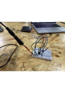
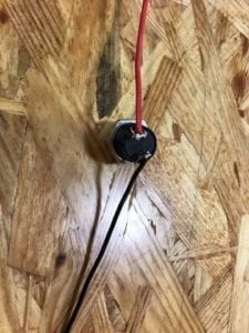
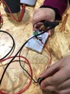
Picture of Door Bell
Circuit 1: Door Bell

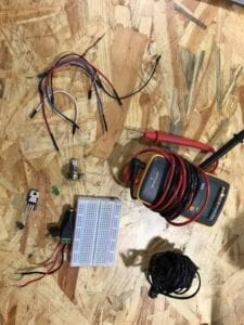
Components:

1 * Breadboard – This is the base for us to connect all the other electrical components together without soldering. There are also connections within the breadboard that we can make use of.

1 * LM7805 Voltage Regulator – To make sure that the current went into the circuit is smooth, we need a voltage regulator so that the buzzer would work. Also, may work with the capacitor to protect other components (LED, buzzer) if there is a sudden blackout.

1 * Buzzer – This component can make sound if connected to electricity. Shall be viewed as the central component of a door bell.

1 * Push-Button Switch/ 1 * Arcade Button – They are two different kinds of switches that can control whether there is electricity in the circuit.

1 * 100 nF (0.1uF) Capacitor – In this circuit, it is the same as a resistor that has an infinite amount of resistance so as the voltage regulator could be connected to ground. Also, the electricity stored in the capacitor may help to protect the LED or buzzer if there is a sudden blackout.

1 * 12 volt power supply – get power from the socket.

1 * Barrel Jack – connect the whole breadboard with the 12v power supply.

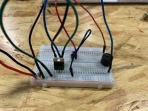
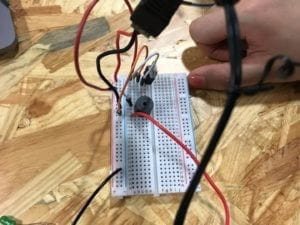
Pictures of the Circuit:
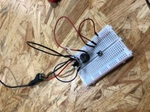
Circuit 1
The first kind of door bell
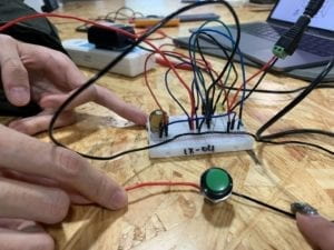
door bell 2
The second kind of door bell

Process:

It is always very difficult to start doing something that I am unfamiliar with. In fact, I have never seen breadboards and never finished a circuit like this before. At the very beginning, my partner and I even thought that we did not need to use electric wires if we put everything on a breadboard since there are built-in connections. However, we immediately realized it was a mistake. After getting more wires, we stuck on the installation of the voltage regulator and capacitor. We tried to connect them via wires but it turned out that we could use the built-in circuit inside the breadboard. To tell the truth this is confusing because we were unsure how to make use of the connection within the breadboard. The next difficulty we faced is the switch. It was really hard to understand why the switch has four pins instead of two before Nick introduced the design of the switch. Anyways, after encountering so many problems, our circuit finally worked and the process of changing the switch into an arcade button went on smoothly since we have already got some sense of building a circuit.

Circuit 2: Lamp
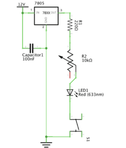
Picture of Lamp
Circuit 2: Lamp

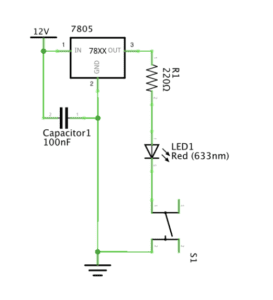
1 * Breadboard – This is the base for us to connect all other electrical components together without soldering. There are also connections within the breadboard that we can make use of.

1 * LM7805 Voltage Regulator – To make sure that the current that went into the circuit is smooth so that the LED would work. Also, may work with the capacitor to protect other components (LED, buzzer) if there is a sudden blackout.

1 * Push-Button Switch – control whether there is electricity in the circuit.

1 * 100 nF (0.1uF) Capacitor – In this circuit, it is the same as a resistor that has an infinite amount of resistance so as the voltage regulator could be connected to ground. Also, the electricity stored in the capacitor may help to protect the LED or buzzer if there is a sudden blackout.

1 * 12 volt power supply – get power from the socket.

1 * Barrel Jack – connect the whole breadboard with the 12v power supply

1 * 220 ohm Resistor – To reduce the voltage connected to the LED and avoid damage.

1 * LED – give out light after electricity flows into the circuit.

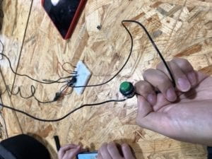
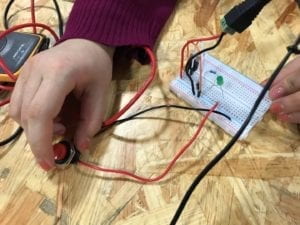
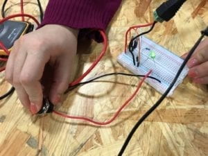
Pictures of the Circuit (My index finger is where the switch was at):
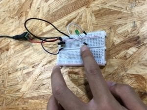
Picture of Lamp
Picture of Lamp

Process:

The process of building a lamp is much easier because we have already built the foundation when building the first circuit. We just need to change the buzzer into a LED light. However, it is important to notice that the positive and negative poles of the LED. The longer pin represents the positive pole and we need to follow the right direction to successfully light it up.

Circuit 3: Dimmable Lamp
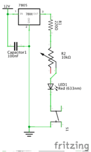
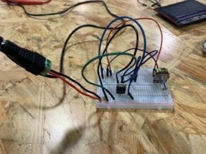
Picture of Dimmable Lamp
Circuit 3: Dimmable Lamp

1 * Breadboard – This is the base for us to connect all other electrical components together without soldering. There are also connections within the breadboard that we can make use of.

1 * LM7805 Voltage Regulator – To make sure that the current that went into the circuit is smooth so that the LED would work. Also, may work with the capacitor to protect other components (LED, buzzer) if there is a sudden blackout.

1 * Push-Button Switch – control whether there is electricity in the circuit.

1 * 100 nF (0.1uF) Capacitor – In this circuit, it is the same as a resistor that has an infinite amount of resistance so as the voltage regulator could be connected to ground. Also, the electricity stored in the capacitor may help to protect the LED or buzzer if there is a sudden blackout.

1 * 12 volt power supply – get power from the socket.

1 * Barrel Jack – connect the whole breadboard with the 12v power supply

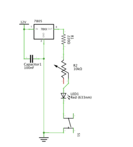
1 *  10K ohm Variable Resistor (Potentiometer) – This resistor allow us to adjust the resistance so as to control the lightness of the LED.

1 * LED – give out light after electricity flows into the circuit.

Pictures of the Circuit:
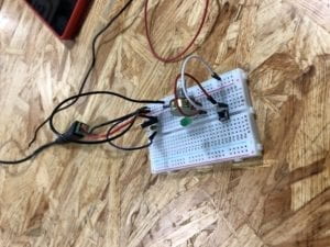
Picture of Dimmable Light

Process:

To convert circuit 2 into circuit 3, we only need to change the resistor into a potentiometer. But initially I did not know why the potentiometer has three pins. I happened to connect the two pins that are seprarated from each other into the circuit and the LED was not on. Later, after receiving some instructions, I found out that I should connect to the two pins on the left and in the middle. In that case, when I rotate the potentiometer, the lightness of LED would change.

Answer for Reflection Question 1:

According to the author, we should define interactivity as “a cyclic process in which two actors alternately listen, think, and speak.” From my perspective, the interactivity of the circuit we built comes from its response when we press the switches. When we implement such an action, the circuit receives a signal. In other words, this is what it could ‘hear’ from human beings. We could hardly say that there is a process of ‘thinking’ within the circuit but after it receives the signal, it answers by turning on the whole circuit and lighting up the LED. I regard this as a way for it to ‘speak’ with us. I think this entire process has met the author’s criteria for interactivity. What is more, for green hands like us to build a circuit often needs communication with others. It would be unlikely for us to complete a circuit solely from the materials on our table. When we have conversations with others about our thoughts on the circuit, this includes interactivity as well. So, I think the circuit itself and the process of building includes two different levels of interactivity but they are both inspiring.

Answer for Reflection Question 2:

In my opinion, there are two ways that physical computing and interaction design can be used to create interactive art. One method is to use physical computing to expand the existing forms of art so that we could see artworks that we would not be able to. An example for this is ‘The Eyewriter.’ The engineers created a method that could help an artist who could not move his body to continue creating graffitis. In terms of art, the work we see is essentially graffiti but the production process involved the intelligence of interaction design and physical computing. Another way that interaction design and physical computing can creat interactive art is to come up with completely different forms of art such as the ‘wood mirror’ that could capture people’s movements by changing colors. Without the help of technology, even if artists have the materials to present the idea, the visual effect and artistic value would not be as good as the one we saw in the film clip. In other words, physical computing helps many artists to put their imagination into reality to the best extent and help them better express their ideas.
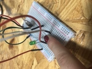
First Lab Post

Lab Date: Feb 15, 2019

Instructor: Marcela

Lab Partner: Julie Huang

Circuit One:

Displaying IMG_1873.jpg

Circuit One Components:

1x Buzzer: Creates beeping sound when there is an electric current flow.

1x 100 nF Capacitor: Acts as a power supply

1x Push Button Switch: Starts or stop connection in the electric circuit

1x LM7805 Voltage Regulator: To regulate and maintain a voltage level. In this circuit it helped transfer 12V voltage level to 5V voltage level

1x Breadboard: A construction base for connecting components

1x 12 Voltage Power Supply: Acts as a stable power source

1x Barrel Jack: Used to connect extra low voltage devices to external electricity.

Jumper Cables: To connect components and pieces.

Where is the power?

While connecting the jumper cables to the breadboard, Instructor Nick spotted a mistake about our circuit. He pointed out the jumper cables that are connected to provide power for the rows and we must connect other jumper cables to those specific rows to create a circuit.

Circuit Two:

Displaying IMG_1876.jpg

Circuit Two Components:

1x Breadboard: A construction base for connecting components.

1x LM7805 Voltage Regulator: To regulate and maintain a voltage level. In this circuit, it helped transfer 12V voltage level to 5V voltage level.

1x Push Button Switch: Starts or stop connection in the electric circuit.

1x Arcade Button: A button that had to be soldered but is able to connect the whole circuit when pressed.

1x 220-ohm Resistor: To reduce current flow

1x LED: Omits light when connected to a power source

1x Barrel Jack: Used to connect extra-low voltage devices to external electricity.

Jumper Cables: To connect components and pieces.

1x nF (0.1uF) Capacitor: To store electrical energy

1x 12V power supply: Provides power source

1x Multimeter: Measures voltage, resistance, and current.

How do you efficiently use the breadboard?

While trying to put circuit two together, we realize the buzzer occupied quite a lot of breadboard space. Therefore my partner and I, with the help of the professors, decided to plant the buzzer on two different sections of the motherboard (as indicated on the picture above). 

Circuit Three:

Circuit Three Components:

1x Breadboard: A construction base for connecting components.

1x LM7805 Voltage Regulator: To regulate and maintain a voltage level. In this circuit, it helped transfer 12V voltage level to 5V voltage level.

1x Push Button Switch: A switch that is able to connect the whole circuit when pressed.

1x 220-ohm Resistor: To reduce current flow

1x 10k oHm Variable Resistor (Potentiometer): To change resistance in a closed circuit.

1x LED: Omits light when connected to a power source.

1x 100 nF (0.1uF) Capacitor: Stores electrical energy.

1x 12 Volt power supply: Provides power source

1x Barrel JackUsed to connect extra-low voltage devices to external electricity.

Jumper Cables: To connect components and pieces.

1x Multimeter: Measures voltage, resistance, and current.

How can we organize our breadboard?

While trying to attempt circuit three, my partner and I quickly realize it was the most complex out of all the challenges. Circuit three required the most jumper cables and cables are confusing and easy to tangle up. Therefore we decided to use different colored cables and spread out the cables in order to make the circuit three easier.

Reflection:

I did not encounter a huge problem trying to put the pieces together for the different circuits. Instead, my partner and I had a more difficult time trying to envision how we can place the components together to achieve the goal. As it is our first time trying to understand how electricity works, we had to consult the professors regarding how we can work out the diagrams. However after we had a general idea/pattern, we learned the ideas and employed it onto the circuits following circuit one.

Answers:

Question One:

After reading the text, I realize the circuits we built today included interactivity as all circuits included an input, an output, and a process. Although these circuits can be considered a lower degree of interaction, it still took two parties to create a reaction. One party is the circuit and the other party being the conductors (my partner and I) pressing a switch. Therefore, I believe our circuits do include interactivity, according to the definition found in the article.

Question Two:

After building the three circuits, I believe we were introduced to the interactive design component but I feel like physical computing is vital to being able to create Interactive Art.  Physical computing and interaction design both involve building interactive software that consists of a stimulus and a response. By creating interactive software that can provide a different response, it attracts users to attempt different stimulus. Especially with technology advancements, the potential templates for interactive art is plentiful and the future is broad.

Interaction Lab – Electronics –

Citlaly Weed

Electronics 

In circuit one we learned to start with the voltage(power) then going clockwise through the whole circuit. The objective was to click the button and there be a buzzing sound. We used a voltage regulator which is a system that maintains constant voltage throughout the circuit. Then we added a speaker so the noise could come out of somewhere, a switch to be able to activate the noise, connecting that to ground (a return path), and lastly connecting the power and ground lines with the capacitor which stores and release its energy much more rapidly. We got this circuit on the first try with guidance from Katie, our amazing guide, so it buzzed immediately.

IMG_8197.TRIM

In circuit two we tried to reproduce what we did in circuit one without the speaker and successfully added the right resistor which is used to reduce current flow, adjust signal levels, to divide voltages. Lastly, adding an LED which did turn on with the button on the first try.

IMG_8199

The third circuit is where we had some trouble being able to dim and brighten the LED (which was the objective). After adding the variable resistor/ potentiometer, an adjustable voltage divider, in between the resistor and the LED we could not figure out why it was not working. It was then pointed out to us that we had forgotten to connect the LED to the button. We plugged it in and then we were finally able to dim and brighten the LED.

IMG_8202

Question one:

After reading The Art of Interactive Design, in what way do you think that the circuits you built today include interactivity? Please explain your answer.

Question one answer:

The creation of the circuits was definitely a form of interaction because of the process of trying to connect wires and other things so once you input electricity into the circuit it would expel the desired output. There was also a more important form of interaction which was between my partner and I. The best example of interaction, given by the author of The Art of Interactive Design, as listening, thinking, and speaking. Without our communication through listening and sharing of ideas the conjoined building of the circuits would not be possible.

Question two:

How can Interaction Design and Physical Computing be used to create Interactive Art? You can reference Zack Lieberman’s video or any other artist that you know .

Question two answer:

Interaction Design and Physical Computing can be used to create Interactive Art in ways that are not only fun but inclusive. Such as in Zack Lieberman’s video where they think of not only design or the computing of the eye sensor so that an artist named Tempt could continue his tagging, but also the inclusivity of design included all sorts of people and price. The design and the physical computing does not have to be restricted to markable products, but something where people and decide to share the fun of art through another medium that is inclusively interactive.


Links Used

https://www.explainthatstuff.com/capacitors.html

Zach Lieberman: Interactive Artist

Interaction Lab: Exercise 1 Documentation — Kenan Gu

Circuit 1: Door Bell

  1. Components:  1) a 12 volt power supply: provide power for the whole circuit

                              2) a LM7805 Voltage Regulator: a transformer that expands the number of             components a single power can connect

                              3) a 100 nF Capacitor: to stabilize and smooth the flow of electricity in this circuit

                              4) a Speaker: make noise to see if the circuit is connected correctly

                              5) a Push-Button Switch: determine the connecting status of this circuit, creating interactivity

                              6) a Breadboard: a basic stage for building the circuit

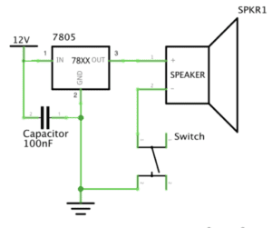
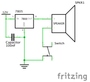
2. Diagram:

3. Pictures and video of the completed circuit:

4. The process of building: We insert the Voltage Regulator first between the positive and negative of the Breadboard. Then we put the Push-Button Switch into this breadboard with its different wires in two different rows. Then we connect the Speaker with one side to the switch and other side to the negative. The circuit worked perfectly as you can see in the video.

Circuit 2: Lamp

  1. Components: 1) a 12 volt power supply: provide power for the whole circuit

                            2) a LM7805 Voltage Regulator: a transformer that expands the number of             components a single power can connect

                            3) a 100 nF Capacitor: to stabilize and smooth the flow of electricity in this circuit

                            4) a LED: if connects with power, it can light

                            5) a 220 ohm Resistor: control the voltage so that the voltage for the LED will not be too much 

                            6) a Push-Button Switch: determine the connecting status of this circuit, creating interactivity

                            7) a Breadboard: a basic stage for building the circuit

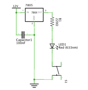
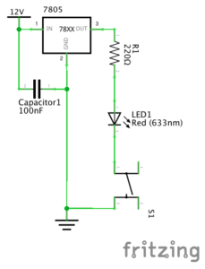
2. Diagram:

3. Picture and video of the completed circuit

IMG_2249

4. The process of building: Based on the foundation of the previous circuit of the speaker, it become slightly easier for us to build this circuit. We just change the speaker to the LED and insert a 220 ohm Resistor between the Voltage Regulator and the LED. We didn’t encounter any issues along the way, which is quite fortunate.

Circuit 3: Dimmable Lamp

  1. Components: 1) a 12 volt power supply: provide power for the whole circuit

                            2) a LM7805 Voltage Regulator: a transformer that expands the number of             components a single power can connect

                            3) a 100 nF Capacitor: to stabilize and smooth the flow of electricity in this circuit

                            4) a LED: if connects with power, it can light

                            5) a 220 ohm Resistor: control the voltage so that the voltage for the LED will not be too much 

                            6) a Push-Button Switch: determine the connecting status of this circuit, creating interactivity

                            7) a Breadboard: a basic stage for building the circuit

                            8) a 10K ohm Variable Resistor: to make the lamp dimmable

2. Diagram

3. Picture and video of the completed circuit:

4. The process of building: Built on the foundation of the previous circuit 2, we just insert the variable resistor between the 220 ohm resistor and the LED. However, the circuit didn’t work first time we tried and the LED can’t be lighted. We then figured out the connection of the circuit was wrong since we connected the positive of the LED to the negative of the 220 ohm Resistor, and the variable resistor’s positive and negative were connected, making the circuit an open circuit. Then we corrected it and the circuit worked good as shown in the video.

Circuit 4: Switch the switches

1. Components: 1) a 12 volt power supply: provide power for the whole circuit

                            2) a LM7805 Voltage Regulator: a transformer that expands the number of             components a single power can connect

                            3) a 100 nF Capacitor: to stabilize and smooth the flow of electricity in this circuit

                            4) a LED: if connects with power, it can light

                            5) a 220 ohm Resistor: control the voltage so that the voltage for the LED will not be too much 

                            6) a soldered arcade button: determine the connecting status of this circuit, creating interactivity

                            7) a Breadboard: a basic stage for building the circuit

                            8) a 10K ohm Variable Resistor: to make the lamp dimmable

2. Diagram

3. Picture and video of the completed circuit:

4. The process of building: Based on the foundation of the third circuit, we just switched the push-button switch to the soldered arcade switch. Circuits worked great as shown in the video.

Questions:

1. From my perspective, the switch in the circuit is the core part of interactivity. Interactivity is defined as “a cyclic process in which two actors alternately listen, think and speak”. The definition shows that interactivity emphasizing on conversations between two entities. In the circuit that we build, the two entities should be people and the reacting item (either the speaker or the lamp). Human like us give out commend by clicking the switch, and the switch turns the open circuit to a closed circuit. Then the speaker start sounding and the lamp start lighting, delivering information we can perceive. Thus, the two entities have conversations and the key part of this conversation to exist is the switch.

2. Just as Zack Lieberman shown in the video. The interaction design and physical computing can      be used in many ways. The interactive painting Lieberman designed that allowed people to play with the whatever drawn in the screen suggests that interaction design can be used to stimulate inspiration in the artistic field. I also see the potential from this case that we can create lots of innovative and funny computer games for enriching our options for entertainment. The second case Lieberman showed in the video is the “Eye Tracker” to help those disabled artists to paint with their eyes. This innovation is really inspiring and significant since it brings up the idea of social responsibility. Trough interaction design and physical computing, we can make complex operations accessible to the disabled, leading to a brighter future for them.    

INTM-SHU 101 – 005 Week 1 Documentation by Sam Li

-Part I. Solder an arcade button

Our group first soldered an arcade button at the soldering station. We used tin and the soldering machine to stabilize wires on both sides of an arcade button, so that the button can be connect with other parts of the circuit. As we were melting the tin, a problem occurred that our soldering machine was not able to melt the tin. Our teaching fellow told us that the problem occured because our soldering machine was oxidized. We changed another soldering machine, and the problem was resolved.

-Part II. Build the circuits

Basic components:

  • Breadboard: A device for connecting multiple components of a circuit
  • A LM7805 Voltage regulator: a device for maintaining a constant voltage level
  • An arcade button: a switch that controls the flow of electricity by turning it on and off
  • A 100nF capacitor: capacitor stores energy
  • A 12 volt power supply: the source of power
  • A barrel jack: connects power supply
  • Several jumper cables: connects multiple components in the circuit and enable electricity to pass through
  • A buzzer: an audio signalizing device. When the user presses the button, the buzzer will create signal of sound
  • A 220 ohm resistor: an electric component that creates electrical resistance in a circuit
  • A LED: a light-emitting diodes, serving as a light source for the user
  • a 10K ohm variable resistor: a device that can be used to adjust the resistance in the circuit, changing the volume of currents passing through

Circuit 1: Door Bell

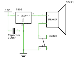
Schematics of circuit 1
  • Components: a breadboard, a LM7805 Voltage regulator, an arcade button, a 100nF capacitor, a 12 volt power supply, a barrel jack, several jumper cables, and a buzzer
  • Process:
    • To build the circuit for doorbell, we put the positive leg (red leg) of power source to the first hole on row 1 and the negative (black) leg to the negative rail (in order that the black wire is connected to the ground and that electricity flows through the divide between leftist columns and middle rows).
    • Second, we use a wire to connect the positive leg of power source to row 1, so that the electricity can go from the left-side columns to the rows in the middle. A voltage regulator and a capacitor are connected in parallel. We used an extra wire to connect the middle leg on voltage regulator to the ground.
    • We then connected the “out” leg of voltage regulator to one leg of our buzzer, using an extra wire. The other leg of the speaker is connected to our arcade button.
    • The arcade button is connected back to the negative column on the left side, so that the circuit is closed.
  • Results and Key learning:
    • After building the circuit, we connect our power source to an outlet. As we press the arcade button, the buzzer creates a “beep” sound.
    • I learned from this process that electricity goes in vertical direction in the leftist two columns and it goes in parallel direction across the rows in the middle.

Circuit 2: Lamp

Schematics of circuit 2
  • Components: a breadboard, a LM7805 Voltage regulator, an arcade button, a 100nF capacitor, a 12 volt power supply, a barrel jack, several jumper cables, a 220 ohm resistor, and a LED
  • Process:
    • We got two resistors for the circuit. In order to pick the 220 ohm resistor, we used the multimeter to test out its resistance.
    • We firstly unplug our power source from the outlet before making changes to the circuit. To build the circuit for our lamp, we took out the buzzer and wires connected to it.
    • Upon unchanged components of the previous doorbell circuit, we use an extra wire to connect “out” leg of the voltage regulator and row 9.
    • Then we put one leg of the 220 resistor on row 9 and the other leg on row 12.
    • One leg of the LED light was connected to row 12 and the other leg on row 18.
    • One leg of the arcade button is connected to row 18, and the other leg of it is connected to the ground.
  • Results and Key learning
    • We connect our power source to the power outlet. When we push the arcade button, the LED light is on.
    • Multimeter is useful for testing the ohm of our resistor.

Circuit 3: Dimmable Lamp

Schematic of circuit 3
  • Components: a breadboard, a LM7805 Voltage regulator, an arcade button, a 100nF capacitor, a 12 volt power supply, a barrel jack, several jumper cables, a 220 ohm resistor, a 10K ohm variable resistor, and a LED
  • Process:
    • We first unplug our power source from the outlet.
    • Upon the previous lamp circuit, we added in a variable resistor between the 220 ohm resistor and the LED.
    • The middle leg of variable resistor is connected to the 220 resistor while the leftist leg (looking from the raised side of variable resistor) is connected to the LED.
  • Results and key learnings
    • We plug in our power source to the outlet, then press the arcade button. The LED light is on when pressing the button. When we turn the variable resistor, we see that the LED light goes dimmer.
    • We learned that the variable resistor could be very useful in controlling the volume of electricity passing through, and thus the lightness of LEDs.

Question 1:

After reading The Art of Interactive Design, in what way do you think that the circuits you built today include interactivity? Please explain your answer.

In response to The Art of Interactive Design, my circuits include interactivity for the following reasons. First, there are two actors involved in the process of interactivity, namely the circuits and their users. Second, the two actors interact in iterative manners. They listen, think, and speak in turns. For instance, when the user interacts with my lamp circuit, the user sees the button. He/she receives the signal that he/she can anticipate a response when pressing the button. The user presses the button. The circuit listens to the signal, it thinks and responses with letting the current go through. Thus, the light will be on.

Question 2:

How can Interaction Design and Physical Computing be used to create Interactive Art? You can reference Zack Lieberman’s video or any other artist that you know .

As shown in Zack Lieberman’s video, creators like Zack uses physical computing to write softwares that process inputs from the physical world and transform them into creative outputs in another form. For instance, in the eye writer project, Zack wrote a software that tracks the movement of human eyeballs to create graffiti. His software and installation then projected patterns of graffiti on huge walls. Interaction happens when the graffiti creator interact with the machine tracking eyeball movements. The audience also interacts with the “Eye Writer” when they receive and react to projected graffiti patterns.