Recitation 1: Electronics and Soldering – Julie (Marcela)

Recitation 1: Electronics and Soldering

Instructor: Marcela

Partner: Justin Wu

Materials Used in Circuits:

  • Breadboard – a flat device used for short term electronic prototyping, that allows for easy and organized connections between jumper cables, etc. without the addition of soldering.
  • LM7805 Voltage Regulator – this maintains the voltage output and is used support the current. For example, this device allows the 12V DC to be executed at 5V DC so the LED would not fry.
  • Buzzer – this device acts as the output once it is pressed, resembling a  feedback system which allowed us to see if our circuit was working or not.
  • Push-Button Switch – this device allows electrical currents to flow throughout the circuit; can act as an input and/or output. 
  • Arcade Button – like the push button switch, this device is another input element that controls electrical flow through the circuit.
  • 220 ohm Resistor – this device limits the voltage that flows to the LED to protect it. 
  • LED – emits light once electricity flows to it; acts as a output.
  • 100 nF (0.1uF) Capacitor – has the same function as the resister; used to protect the LED or buzzer.
  • 10K ohm Variable Resistor (Potentiometer) – this device can adjust the voltage that flows to the LED, controlling the brightness of the LED.
  • 12 volt power supply – we converted the 220V AC to 12V DC, a voltage level that was safer to experiment with.
  • Barrel Jack – connects the breadboard with the 12V DC power supply. 
  • Multimeter – ahas many different functions, but in this class, we used it to determine the correct resister level.
  • Several Jumper Cables (Hook-up Wires) – flexible wires used in the breadboard to connect circuits.

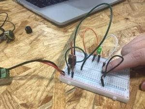
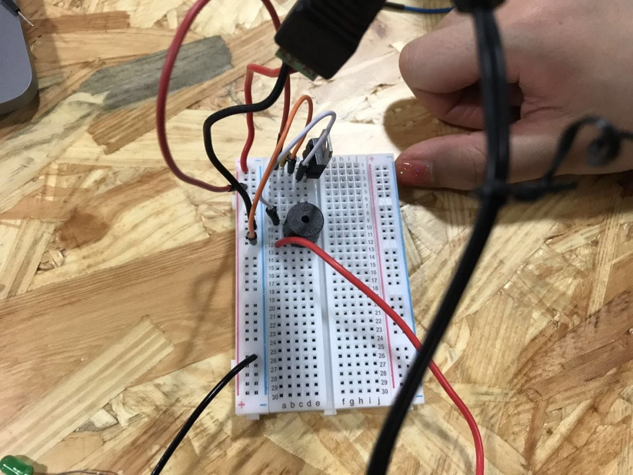
Circuit 1: Doorbell
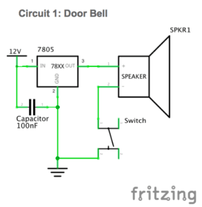
Components used:  Breadboard, LM7805 Voltage Regulator, Buzzer, Push Button Switch/Arcade Button, 100 nF (0.1uF) Capacitor, 12 volt power supply, Barrel Jack

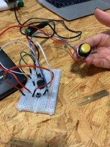
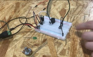
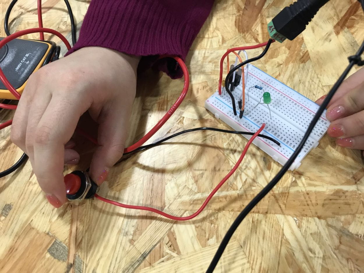
While this model seemed fairly simple, it really helped me understand how the breadboard flow works and the concept of power and ground. Our first few trials were all failures. Being new at this, we weren’t really sure how to go about the circuit. We weren’t sure how to connect everything and what was connected to what. But once the functionality of the breadboard was explained to us, we were able to rearrange our jumper cables to connect the correct cables to power, ground, and legs of the components. We were also learned that the best way to format the button was to have the jumper cables in a cross formation, and that it would cancel out if the cables were in the same row. 

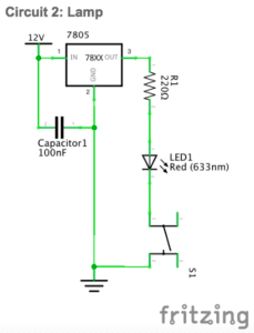
Circuit 2: Lamp
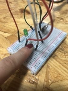
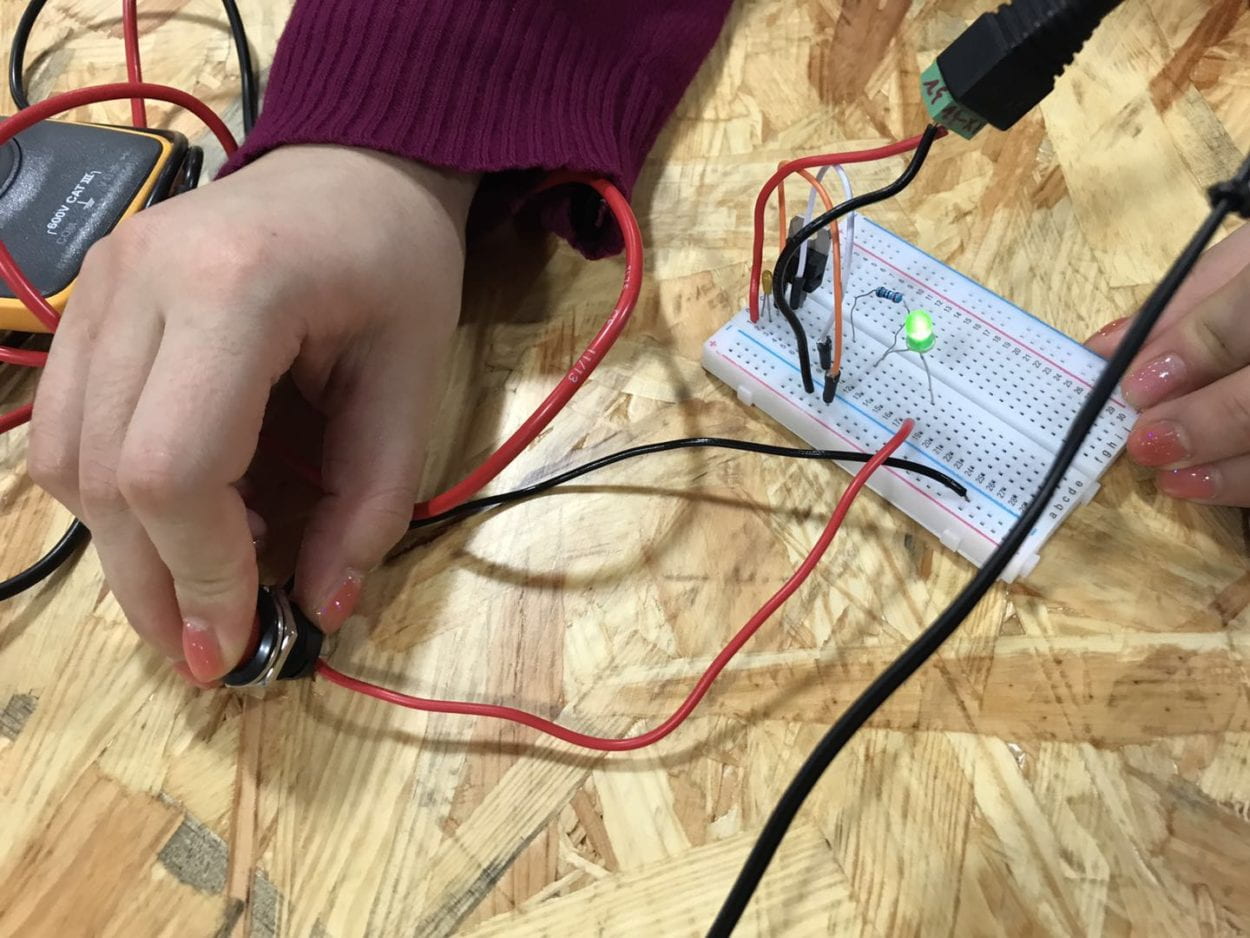
*finger on the button

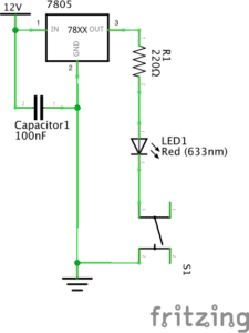
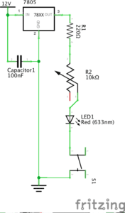
Components used: Breadboard, LM7805 Voltage Regulator, Buzzer, Push-Button Switch/Arcade Button, 100 nF (0.1uF) Capacitor, 12 volt power supply, Barrel Jack, 220 ohm Resistor, LED

After assembling the first circuit, we had a much easier time with this circuit, We just replaced the buzzer aspect with the LED light. However, we had to be careful of the legs of the LED light and remember that the long leg is positive to power. Only if the legs are positioned correctly, then the LED would light up. 

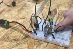
Circuit 3: Dimmable Lamp
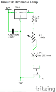
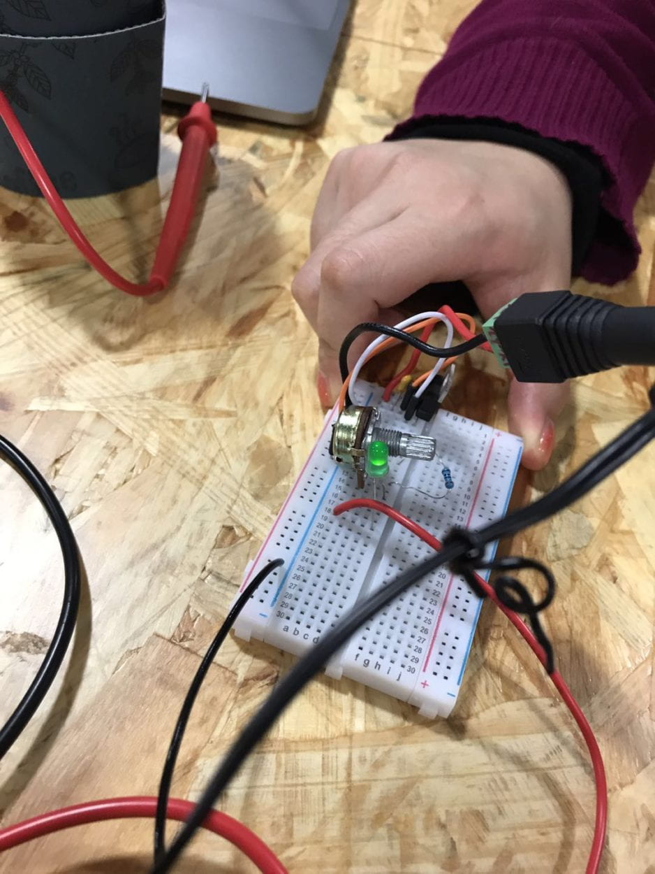
Components used: Breadboard, LM7805 Voltage Regulator, Buzzer, Push-Button Switch/Arcade Button, 100 nF (0.1uF) Capacitor, 12 volt power supply, Barrel Jack, 10K ohm Variable Resistor (Potentiometer), LED 

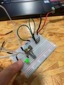
In this experience particularly, I think we realized the importance of breadboard organization. When we first began, we had a lot of jumper cables hanging out and plugged in with no purpose. It was difficult to see what line the potentiometer legs were plugged into. We replaced the resistor with the potentiometer, but were initially confused where to plug what because it had 3 legs. However, after further instruction, we were told to plug the cables into the left and middle legs. From there, we were able to light up and adjust the LED brightness.

Soldering!
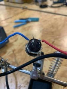
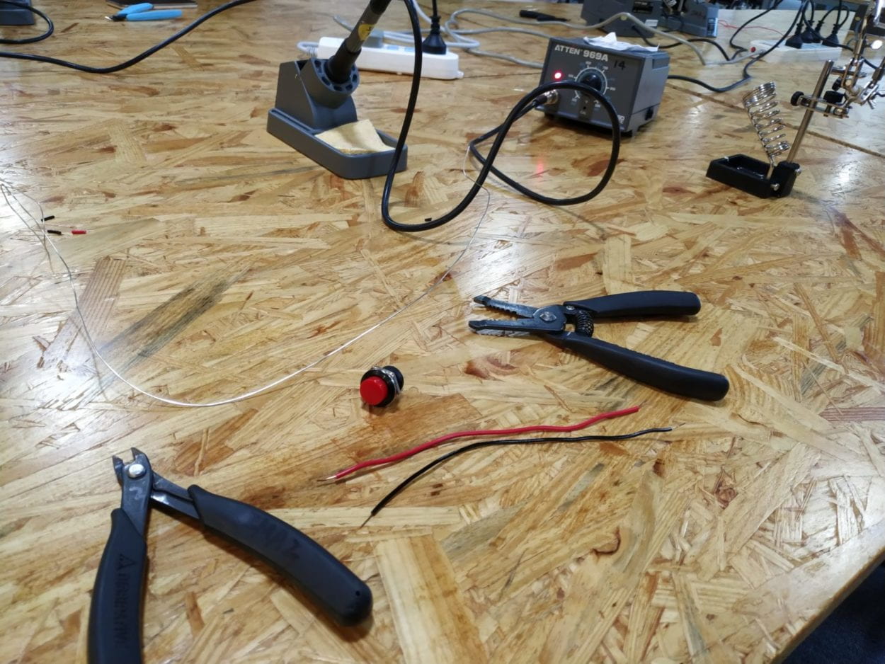
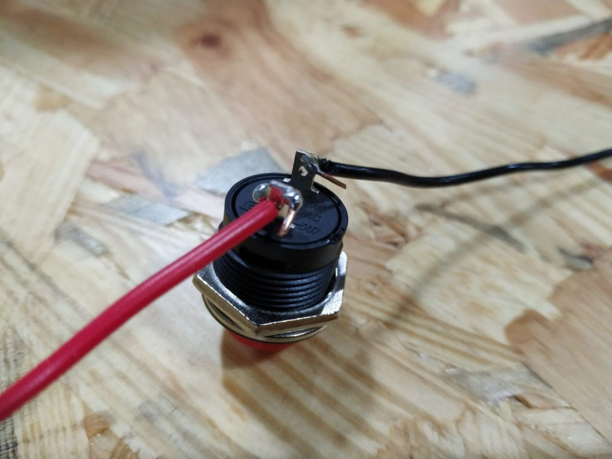
While we only used this button in the first circuit, this was my favorite part of recitation. We were able to solder the wires onto the connecting metal circles to facilitate electrical flow by melting a little portion of the metal jumper cable.

Reflection Question 1:

After reading The Art of Interactive Design, I believe our circuits include interactivity through the cycle of human interaction and feedback. The author describes interactivity as a cycle where “two actors alternately listen, think, and speak.” In this case, both my partner and I were one actor and the breadboard circuit was the other actor. We would listen to the instructions given, think about how to format the elements, and speak to the breadboard by trying the circuit out. The circuit would then have to listen to our ideas, think if the ideas were suitable, and speak back to us, giving us feedback if the circuit was functioning or if something was wrong (ie. no buzzing or light). If something was wrong, we would then have to listen to what the circuit was doing (usually nothing), and if nothing was happening, we would then have to think about how to make it work, and ultimately speak again and execute what we thought would work. This cycle is a continuous loop of listening and feedback until both actors are satisfied with the outcome. 

Reflection Question 2:

Interaction Design and Physical Computing can be used to create interactivity in numerous fashions. Both interaction design and physical computing have been around for ages, but in our most recent era, we have had the breakthrough of being able to combine both aspects to create interactive ideas with humans, other objects, etc. For example, interactive design can enhance existing ideas. In class, we watched this particularly eyeopening video “The Eyewriter”. This particular film really stood out to me because not only was this using physical computing to help someone, but that computing led to interactive design that changed his life. Being physically disabled left him constrained to his bed, but with this idea, he was essentially able to be transported outside and have his graffiti shown on buildings miles away from him, allowing him to interact with many other humans. However, I think interactive design and physical computing can also be for silly things like the head button game where 2 players wear helmets and try to slap each others head and have their picture taken when the button is pressed. Both ideas are great and create interactivity with each other and with physical things. The range of ideas to create interactivity is immense and can be for all different purposes. 
Recitation 1:Electronics and Soldering(Alex Wang)

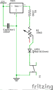
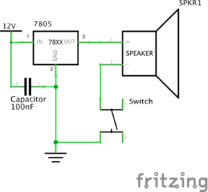
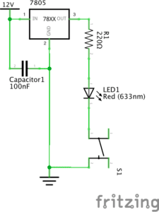
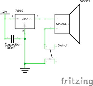
Week 1 Recitation is on basic circuits and soldering. We are tasked with the construction of three different circuits, door bell, lamp, dimmable lamp and replacing one of the buttons with an arcade button.(Schematics below)

Process:

The overall process went very smooth, even when both me and my partner had minimal experience in hardware. The circuit wasn’t functioning properly a few times during our construction(mostly loose connection on the breadboard) but we were able to track down the problem by using the sound function on the multimeter fairly easily.

Videos of all working circuits, including arcade button modification

:

Reflection:

I think this recitation was a very good way of getting us started with electronics. I was a bit confused at first, but with the provided schematics and the reference pictures I was able to figure everything out fairly easily. To be able to make something that works feels very satisfying and fun.

Documentation Questions:

Q1:After reading The Art of Interactive Design, in what way do you think that the circuits you built today include interactivity? Please explain your answer.

I understand interactivity as giving a wanted feedback when given certain action, just like the input and outputs of a circuit or program. As for the circuits we have built in this weeks recitation, we interact with the electronics by pressing on a button or turning on a knob, and in response the electronics would give back a beep or a flash for us to know its functioning.

Q2:How can Interaction Design and Physical Computing be used to create Interactive Art? You can reference Zack Lieberman’s video or any other artist that you know.

My personal interpretation of how art is different from other things is how it has meaning behind it, or the ability to give people certain feelings. And implementation of interactivity with the use of sensors can enable the user to experience art through an medium that gives more interaction to the whole body as opposed to just watching a movie or listening to a song.

Recitation 1: Electronics & Soldering By Haoquan Wang (Chung)

Recitation 1: Electronics & Soldering

Partner: Nathan Wang

Date: 15th February

Circuit 1: Doorbell

Components:

Breadboard, LM7805 Voltage Regulator, Push-Button Switch, speaker, 100 nF (0.1uF) Capacitor, 12-volt power supply, wire

Functions of each component:

LM7805 Voltage Regulator: maintain a constant voltage level.
Breadboard: provide a base for making electronic connections
Capacitor: stabilize and smooth the flow of electricity, store the current
Speaker: make sound
Switch: interrupt the flow of current through a circuit
Wire: enable the current to flow
12-volt power supply: supply power

The problem we encountered: At first we did not understand how the wires inside the breadboard are connected and work, which makes us do not know how to start. With the help of a learning assistant, we successfully compared the circuit diagram to the breadboard and made it.

Circuit 2: LED

Components: Breadboard, LM7805 Voltage Regulator, Push-Button Switch, 220-Ohm Resistor, LED, 100 nF (0.1uF) Capacitor, 12-volt power supply, wire

Functions of each component:

Breadboard: provide a base for making electronic connections
Resistor: control the flow of current, protect the LED from being burnt
Capacitor: stabilize and smooth the flow of electricity, store the current
LED: shine
Switch: interrupt the flow of current through a circuit
Wire: enable the current to flow
12-volt power supply: supply power

The problem we encountered: Our switch was broken at first, we put it into our circuit but it did not work for no reason. We checked our circuit over and over aging but still cannot light the led. Even the learning assistant could not figure out where the problem is. But luckily we found out that the switch was broken.

Circuit3:

Component: Breadboard, LM7805 Voltage Regulator, Push-Button Switch, 100 nF (0.1uF) Capacitor, 12-volt power supply, wire, Variable Resistor, LED

Functions of each component:

Breadboard: provide a base for making electronic connections
Resistor: control the flow of current, protect the LED from being burnt
Capacitor: stabilize and smooth the flow of electricity, store the current
LED: shine
Switch: interrupt the flow of current through a circuit
Wire: enable the current to flow
12-volt power supply: supply power
Variable Resistor: adjust the amount of resistance

Process:

We changed several components from the last circuit and successfully made it work.

Question 1:

I think the switches are the interactive part in our circuits. Because we can control the doorbell and lead by pushing the switch. This process includes input and output. We can get feedback from circuits by our motion input. That is a reciprocal process.

Question2:

In my opinion, for Interactive art, we need to address the reciprocal process in the physical computing design. Because interaction is at some rate a two-sided activity. Hence we can design circuits to be able to be controlled by using switches or variable resistors, which can provide different forms of interaction such as the speaker makes a sound and the LED is lighted.

Recitation 1: Electronics & Soldering- Gloria (Yixuan Liu)

Partner: Julia (Qianyue Fan)

Circuit 1:

Breadboard: the platform for connecting the circuit

12-volt power supply: providing electricity for the circuit

Voltage Regulator: adjusting the voltage to make it close to the value needed by the circuit

Buzzer: a signal to show the circuit has electricity and is complete by making sounds

Push-Button Switch: controlling whether the current can go through, deciding whether the circuit is cut or not

Capacitor: storing electricity when the current goes in, and releasing energy when the circuit is without the current

Circuit 1 Diagram
Circuit 1

Building this circuit was really difficult for me since it was the first time that I had ever seen a breadboard. Therefore, we spent some time figuring out the function of each part of the breadboard. At first, we were confused about the voltage regulator, because we were not sure about the function of the three feet of it. With the help of the instruction, we set the voltage regulator correctly. Later, we did not know how to set the button, since it has 4 corners to be connected with 2 wires. With the help of an IMA fellow, we learned that we have to test which two corners to use by using a multimeter. Only if the number remains 0 can we use the tested 2 corners on the button, otherwise the LED would be on before pressing the button. Then we set the capacitor and finished this circuit.

Circuit 2:

Breadboard: the platform for connecting the circuit

12-volt power supply: providing electricity for the circuit

Voltage Regulator: adjusting the voltage to make it close to the value needed by the circuit

LED: making sure that the electricity goes in a single direction, and showing whether the circuit is complete and correct or not

Push-Button Switch: controlling whether the current can go through, deciding whether the circuit is cut or not

220-ohm Resistor: limiting current to protect the circuit

Capacitor: storing electricity when the current goes in, and releasing energy when the circuit is without the current.

Circuit 2 Diagram
Circuit 2

It was easier to build this circuit since we were kind of familiar with the breadboard. However, with too many components in the same circuit, it is hard to judge where to put the wires. At first, we thought our circuit was correct, but actually, we did not notice that there was a spare line connecting the capacitor and the power supply. Therefore, it is important to check whether all of the wires are necessary after building it.

Circuit 3

Breadboard: the platform for connecting the circuit

12-volt power supply: providing electricity for the circuit

Voltage Regulator: adjusting the voltage to make it close to the value needed by the circuit

LED: making sure that the electricity goes in a single direction, and showing whether the circuit is complete and correct or not

220-ohm Resistor: limiting current to protect the circuit

Variable Resistor: having adjustable resistance for the current

Push-Button Switch: controlling whether the current can go through, deciding whether the circuit is cut or not

Capacitor: storing electricity when the current goes in, and releasing energy when the circuit is without the current.

Circuit 3 Diagram
Circuit 3 

We finished this circuit quickly, because it was based on the previous circuit, and we only need to add a variable resistor. With the reminder of a fellow, we plug off the circuit to avoid getting shocked when making adjustments to the circuit. However, the circuit did not work even if it seemed correct. Later, we found out that we put the pins of the voltage regulator into the wrong holes, and we turned the variable resistor to its biggest value. After fixing these problems, the LED light was on.

Question 1:

After reading The Art of Interactive Design, in what way do you think that the circuits you built today include interactivity? Please explain your answer.

According to the reading, interactivity contains two actors, and they respond to each other’s action back and forth. For the circuits I built with my partner, the two actors are people and the circuit. When the circuit is completed, people get the signal that it can work, responding to it by pressing the button. The circuit responded to people’s action by letting electricity go throw, lightening the LED.

Question 2:

How can Interaction Design and Physical Computing be used to create Interactive Art? You can reference Zack Lieberman’s video or any other artist that you know.

Interaction Design and Physical Computing can be used to create Interactive Art, by building interaction between human body and computer. They exaggerate and concretize people’s inner incentive and emotion. A computer can react to the energy given off by bodies, and bodies can give different choices reacting to different signals given by the computer. According to Zack Lieberman’s project, Eye-writer, Interaction Design, and Physical Computing were used to help people who are not able to move to create arts. Therefore, Interaction Design and Physical Computing can be used to enable people who are unable to move to express themselves through a more convenient way, and concretize people’s inner feeling, artistic thoughts, and abstract emotion, by setting computers to react to and transform the energy given off by bodies.

Int Lab Recitation 1–Weiyi He(Molly)

Lab Date: Feb 15, 2019
Instructor: Marcela
Lab Partner:
 Sam Li

Aim of Today’s Lab: build three sets of circuits using the breadboard and learn how to solder.

Circuit 1: Door Bell 

Components:

  • 1 * Breadboard–A pre-organized cable layout, easy to plug in jumper cables and other units’ legs. Good for organizing circuit. 
  • 1 * LM7805 Voltage Regulator–Turns 12V DC to 5V DC. This, with the power supply, gives our buzzer and LED a friendly 5V. 
  • 1 * Buzzer–Output. Add direct current and it plays a 2200 Hz pitch.
  • 1 * Arcade Button–Input. Switch on and the current can pass
  • 1 * 100 nF (0.1uF) Capacitor–Stores electricity while current is flowing into them, then releases the energy when the incoming current is removed. Capacitors can also be used to stabilize and smooth the flow of electricity.
  • 1 * 12 volt power supply–Turns 220V AC to 12V DC. 
  • 1 * Barrel Jack–Convert the power in the cable into the form that the breadboard can process with
  • Several Jumper Cables (Hook-up Wires)–Help with connecting the circuit

1

Circuit 2: Lamp

Components:

  • 1 * Breadboard
  • 1 * LM7805 Voltage Regulator
  • 1 * Arcade Button
  • 1 * 220 ohm Resistor–Help reduce the current and share the voltage so that the LED won’t pop.
  • 1 * LED–Output. Polarized. Consume electricity and emits light.
  • 1 * 100 nF (0.1uF) Capacitor
  • 1 * 12 volt power supply
  • 1 * Barrel Jack
  • 1 * Multimeter–Test the resistance of the resistors.
  • Several Jumper Cables (Hook-up Wires)

2

Circuit 3: Dimmable Lamp 

Components:

  • 1 * Breadboard
  • 1 * LM7805 Voltage Regulator
  • 1 * Arcade Button
  • 1 * 220 ohm Resistor
  • 1 * LED
  • 1 * 100 nF (0.1uF) Capacitor
  • 1 * 10K ohm Variable Resistor (Potentiometer)–Control the brightness of the LED using the change of the resistance.
  • 1 * 12 volt power supply
  • 1 * Barrel Jack
  • Several Jumper Cables (Hook-up Wires)

3

Problems:

  1. Don’t know which is the front of the capacitor: the front is with the black box that sticks out.
  2. The negative is seen as the ground.
  3. The power should better be inserted into the very left/right column with specific signs of +/-
  4. Each row should be connected with cables.
  5. The very left/right column is not connected to the middle two columns.
  6. Always plug out the device when altering the circuit.
  7. The capacitor is both in parallel and series connection.

We’d also tested the push-button switch and found out that of the 4 legs of the switch, the diagonal 2 work to serve as a switch.

Soldering part

Tools:

Soldering iron: set to a specific degree

Soldering stand

Wire cutter and wire stripper

Problems:

  1. The tip of the soldering iron has some oxide coating and it increases the difficulty of melting the solder. To avoid failure, solder for a longer time/use steel wool to clean the oxide coating/don’t touch the oxidic parts of the iron 
  2. I burned some of the outer of the wire. Correction: Be careful.

Answers to the questions

1. For the first two circuits, if you push the button (or switch), the circuit gives feedback: either buzzing or lighting up the LED. For the third one, if you turn the handle of the potentiometer while you push the button, you can control the brightness of the LED. The users can interact with the buzzer/LED with the help of the circuit.

2.

Yayoi Kusama

Infinity Mirrored Room -The Souls of Millions of Light Years Away, 2013

wood, metal, glass mirrors, plastic, acrylic panel, rubber, LED lighting system, acrylic balls, and water
 
The result is a distinctly visual immersion and a counterpoint to the rooms that envelope the viewer. Through extreme repetition, it creates phenomenological experiences that provoke a sense of boundlessness and transcendence.