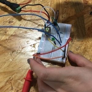
Week 1: Recitation Documentation – Theresa Lin (Marcela)

Recitation Date: 2/15/19

Instructor: Marcela Godoy


Circuit 1: Door Bell

Materials:

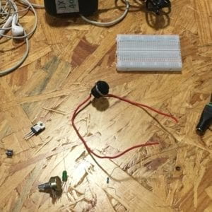
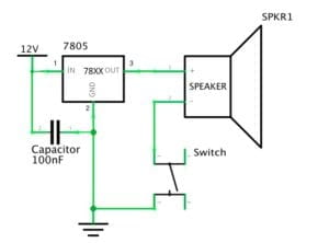
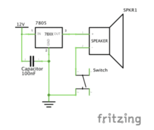
1 * Breadboard,  1 * Buzzer,  1 * LM7805 Voltage Regulator,  1 * Push-Button Switch,  1 * 100 nF (0.1uF) Capacitor,  1 * 12 volt power supply,  1 * Multimeter,  Several Jumper Cables (Hook-up Wires),  1 * Barrel Jack

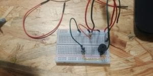
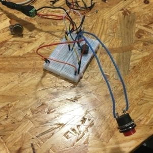
At first, we had no idea how to use the breadboard. So instead of using it, we tried to connect each component directly with the wires and quickly realized that was a mistake. With the help of some fellows, we were given a quick rundown on how to use the breadboard.

When the circuit was first completed, it did not work because the voltage regulator was not properly connected to the speaker and capacitor. We only connected one wire from the regulator to the voltage, and tried to connect the regulator with the speaker and capacitor without wires.
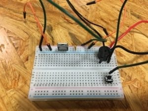
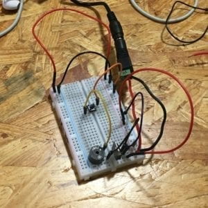
After finally fully grasping how to use wires and the breadboard, the circuit was properly completed. Although the speaker did go off, the switch did not work. When we pressed the switch, it couldn’t turn the speaker on and off like it should. So after some close inspection and help from the fellows, we noticed that the switch was not put in correctly. After that was solved, the switch finally worked.
Circuit 2: Lamp

Materials:

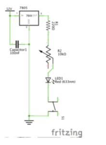
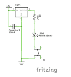
1 * Arcade Button,  1 * 220 ohm1 * Breadboard,  1 * LM7805 Voltage Regulator,  1 * Push-Button Switch,  1 * 100 nF (0.1uF) Capacitor,  1 * 12 volt power supply,  1 * Multimeter,  Several Jumper Cables (Hook-up Wires),  1 * Barrel Jack

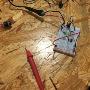
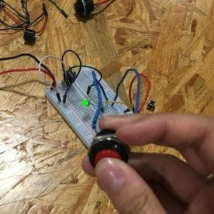
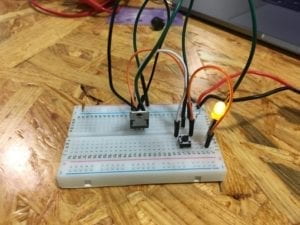
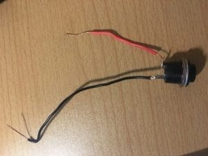
This time, building the circuit went smoothly. Before constructing the circuit though, we tested to see which resistor had 220 Ohms with the multimeter. After we built the circuit, we tested it but the LED didn’t light up so we double checked all the wires and position of the components. It turned out that the LED light was not put in correctly. The positive and negative was put in the other way around. After we fixed that, the LED lighted up and the switch also worked. For this circuit, we tried replacing the switch with the arcade button we soldered and that also went smoothly.
Circuit 3: Dimmable Lamp

Materials:

1 * Arcade Button,  1 * 220 ohm1 * Breadboard,  1 * LM7805 Voltage Regulator,  1 * Push-Button Switch,  1 * 100 nF (0.1uF) Capacitor,  1 * 12 volt power supply,  1 * Multimeter, Several Jumper Cables (Hook-up Wires),  1 * Barrel Jack, 1 * 10K ohm Variable Resistor (Potentiometer)

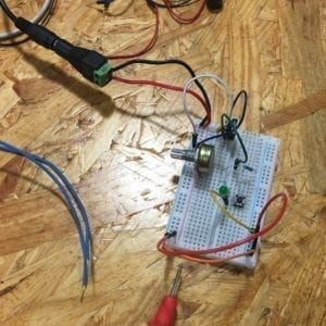
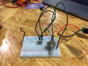
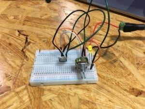
By now, we had no problem putting together the circuit. We tested how the dimness of the LED light would change if we plugged the wire into the different parts of the variable resistor. We found out that the dimness level actually changes.
Reading Response:

The circuits that we built during recitation included interactivity because the LED light gave feedback when we pressed the button. However, as mentioned in “The Art of Interactive Design” feedback from machines like a light lighting up in a fridge or from the LED light in our case, is an example of a low level of interactivity. The circuit with the highest interactivity would probably be the last circuit where we were able to change the level of dimness by plugging the wire into different parts that were connected to the variable resistor.

Interaction design and physical computing can act as tools to create interactive art. The product that Zack Lieberman created the EyeWriter which enables Tony, a graffiti writer, who is paralyzed to be able to write graffiti with just his eye. The Eyewriter allows Tony to once again be able to interact with his environment by writing graffiti. This just shows that physical computing can create tools that allow humans to interact with their surrounding.
Week1: Recitation Documentation-Kaycee(Yijia Chen)

Partner: Zhiqiu Wang

Instructor: Young

Circuit1 Door Bell

Components and their functions:

Push button: connect/disconnect the circuit to let the electric current pass/not pass to control the on/off of the speaker

12V power:  provide power for the whole circuit

Speaker: make sound

Capacitor: store electricity, let the electric current change slowly to protect the circuit

Wire: connect different components of the circuit

Voltage regulator: regulate voltage

Breadboard: fix all components and provide connections between them

The process of building the circuit:

At first, we’re confused because it was the first time for both me and my partner to use a breadboard. Therefore, we have to ask for help to figure out how this component worked. Things got more smoothly after we got familiar with the inner structure of the breadboard. We built the circuit and adjusted some of the wire under the guidance of professors, but to our disappointment, when we pushed the push button, the speaker didn’t make any sound. We together with professors tried to find the problem by testing each component of the circuit but failed to figure it out. Therefore, we picked another set of all components and test our circuit again. This time it worked.

Circuit 2: Lamp

Components and their functions:

12V power:  provide power for the whole circuit

Voltage regulator: keep the voltage at a stable number

Capacitor: store electricity, let the electric current change slowly to protect the circuit

Wire: connect different components of the circuit

Breadboard: fix all components and provide connections between them

Push button: connect/disconnect the circuit to let the electric current pass/not pass to control the on/off of the LED

LED: shine

220-ohm resistor: ensure the current is running within a safe range

The process of building the circuit:

Since the first circuit has provided us with some basic knowledge of how the breadboard works, we connected the whole circuit quickly and adjusted fewer than before since fewer mistakes took place. However, when we pushed the button, the LED didn’t light up as we expected. We still seek help from instructors but again, he couldn’t tell where was the problem thus we had to change another set again. Luckily, the LED light up in our second try.

Circuit 3: Dimmable Lamp

Components and their functions:

12V power:  provide power for the whole circuit

Voltage regulator: keep the voltage at a stable number

Capacitor: store electricity, let the electric current change slowly to protect the circuit

Wire: connect different components of the circuit

Breadboard: fix all components and provide connections between them

Push button: connect/disconnect the circuit to let the electric current pass/not pass to control the on/off of the LED

LED: shine

Variable resistor: change the resistance to change the amount of current

The process of building the circuit:

This time the process went quite well since we used the same set in circuit 2 so every component can be guaranteed working normally. And we only added a variable resistor. The brightness of LED can be witnessed changed obviously when we rotating the variable resistor.

Question 1:

After reading The Art of Interactive Design, in what way do you think that the circuits you built today include interactivity? Please explain your answer.

According to my understanding of The Art of Interactive Design, interactivity is two or more agents respond to each other’s action. This process includes first understanding the other’s action and then react to it and then flipping the order to form a loop. In our practice, I think the stitch shows this kind of interactivity because when people push the button, the circuit is closed and current flows to make the speaker or the LED works. It understands and responds to people’s action of pushing the button.

Question 2:

How can Interaction Design and Physical Computing be used to create Interactive Art? You can reference Zack Lieberman’s video or any other artist that you know.

Because interactive art is an activity relates more than one single agent. Therefore, the more controllable parts in the circuit, the more degree of interactivity it shows with people. We can build more components which can be adjusted or controlled by people into the circuit or any other physical computing program to increase the interactivity.

IMA Week One- Nate Hecimovich

Partner: Dominick Nardone

Circuit 1: Doorbell 

To make this circuit we followed the instructions using a button, a speaker, a voltage regulator, and a capacitor.  When constructing this circuit we ran into an initial problem, we had the voltage regulator going horizontal across the breadboard instead of vertically. 

We had the voltage regulator turned in the wrong direction restricting the flow of electricity making it impossible to complete the circuit.

However, once we figured out the problem with the voltage regulator we quickly corrected the issue and our doorbell worked.

Circuit Two: Lamp

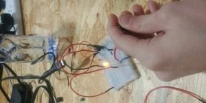
We had a much easier time with this circuit now that we had figured out the voltage regulator situation.  However, for this project we included a resistor to prevent the LED from frying.  Based off of the knowledge acquired on the first project this one came very easily. 

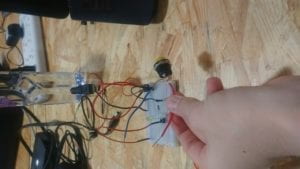
(Apologies for the terrible quality of this photograph)

Circuit 3: Dimmable Lamp

This circuit was made by replacing the voltage resistor with a variable resistor allowing us to make the light more intense and also dimmer by turning the knob.  (Photo not available for this part)

Circuit 4: Arcade Button Lamp

This one was simple as we just replaced the basic button for this arcade button soldered onto two wires.  By removing the button for the arcade button it made it way more fun and interactive.

Questions:

Our circuits were interactive in the fact that we were communicating with it and it was communicating back to us by either working or not working.  By listening to the circuit we were able to make corrections and eventually arrive at the final solution in which it would listen to us flawlessly.  Through communication on both ends as stressed in the reading we created “interactivity”

By combining the concepts of interactive design and physical computing we as a species can tackle problems that used to be unsolvable.  This opens up new frontiers of exploration, and also opportunistic to help people in all walks of life.  One example that was demonstrated this perfectly was the play station device created by NYU students for the severely disabled adolescent which allowed him to play baseball games without physically having to do the movements necessary to do it the conventional way.  There are so many doors that are opened up by the combination of both of these concepts whether it be just for fun and games or actual, meaningful societal contributions.

Recitation 1: Documentation by Robin Luo

Lab Date: Feb. 15, 2019
Instructor: Marcela
Lab Partner: Ivy

Aim of Today’s Lab: Learn how to solder an arcade button and complete three circuits using a breadboard.

Soldering arcade button

Process: 
In this exercise, we soldered an arcade button. We soldered two jumper cables to our button by melting a metal wire to our cables. We also used pilers to expose some of the copper to help us solder the metal to the cable. 

Circuit 1: Door Bell

Materials used:
Breadboard, Speaker/Buzzer, Capacitor, Push-Button Switch,
LM7805 Voltage Regulator, 12 volt Power Supply, Barrel Jack, Jumper Cables 

Process:
I was pretty intimidated beginning this exercise as my partner and I had no experience and didn’t know where to begin, so we began by asking fellows a lot of questions the breadboard, how to use it, and about some of the materials we acquired in the exercise. After assembling the circuit by ourselves according to the schematic, we ran into some problems. Consulting several fellows, we found out our capacitor was in the wrong place so we moved it next to our jumper cables in the power rails. We also found out that our voltage regulator was in the incorrect order so we fixed the jumper cables into the correct order. After fixing these issues, our circuit worked.

With Arcade Button

Circuit 2: Lamp

Materials used:
Breadboard, LED, 220 ohm Resistor, Capacitor, Push-Button Switch, LM7805 Voltage Regulator, 12 volt Power Supply, Barrel Jack, Jumper Cables

Process:
There was not much change between the door bell circuit and the lamp circuit. For this circuit, we exchanged the speaker/buzzer for the LED and 220 ohm resistor and rearranged the position of our capacitor and jumper wires. We tested both resistors by using the multimeter to determine which was the resistor we needed. There wasn’t much trouble building this circuit. However, we realized when building this circuit that we needed to exchange our push-button switch with the arcade button we had soldered from earlier. Although when we tried our arcade button, the LED failed to turn on. After consulting a fellow, we exchanged our arcade button with another one as the wires to our buttons were suspected to be burnt when we were soldering. We also learned how a push button worked and how to place it in our breadboard despite the fact our guesses on how to use it were correct. Our circuit worked again.

With Arcade Button

Circuit 3: Dimmable Lamp

Materials used:
Breadboard, LED, 220 ohm Resistor, 10K ohm Variable Resistor, Capacitor, Push-Button Switch,
LM7805 Voltage Regulator, 12 volt Power Supply, Barrel Jack, Jumper Cables
dimmable light

Process:
There was not much issue with this circuit. We added the 10K ohm variable resistor and rearranged the position of our jumper wires. Tested the circuit with both buttons and it worked perfectly! We returned to our door bell circuit and tried it with the arcade button as well.

With Arcade Button

Conclusion
I learned so much during this recitation: what a breadboard does, how to use it, how it works, and how to read schematic diagrams and build simple circuits like the ones we did. Without prior experience, it also confirmed by beliefs that if you don’t know something, there are always resources out there to help you and questions to ask. Some mistakes we had during this exercise was understanding how certain components worked (capacitor, voltage regulator, buttons) and how to implement it into our circuits. We also learned some other tips such as using two different colored wires for our arcade button to tell the difference between our ground and power connections. All in all, this exercise made me excited for what’s to come in this class.  

Answers to Questions
After reading The Art of Interactive Design, in what way do you think that the circuits you built today include interactivity?

The Art of Interactive Design describes interactivity as at least two purposeful actors that react to one another. After reading this article, the circuits we built in this recitation in my opinion include interactivity because we can interact with it and it will respond to our actions. With the doorbell and lamp circuit, we could press a button which emitted a sound or turned an LED light on and allow these reactions to turn off when we release the button. With the dimmable lamp, we could not only press and release a button which to turn on and off the light, but we could also change the brightness of the LED light.

How can Interaction Design and Physical Computing be used to create Interactive Art? You can reference Zack Lieberman’s video or any other artist that you know.

Interactive Design and Physical Computing can be used to create Interactive Art in all kinds of ways. One example of Interactive Art using Interactive Design and Physical Computing is Dialect for a New Era by Frederik Duerinck and Marcel Van Brakel which I experienced in the Cooper Hewitt last summer. This work of art uses Interactive Design by allowing the user to press a button on a glowing square pillar which in turn emits a scent allowing the user to smell. It uses Physical Computing through the button as well. The button is the input and in turn the piece understands to output a smell through holes above the button.