Interaction Lab – Recitation 1 (Kyle Brueggemann)

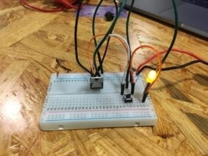
During our first recitation, we worked on soldering different wires together as well as constructing three basic circuits in order to better understand the functions of different electrical components.

Components:

Breadboard: A layout of conductive terminals that facilitates the creation of the circuit by providing a consistent cable design.

12 Volt Power Supply: Plugs into an electrical outlet and provides the electrical source for the circuit.

LM7805 Voltage Regulator: Maintains a constant voltage level so the buzzer and LED can operate as efficiently as possible.

100 nF Capacitor: Assists in the functioning of the voltage regulator by acting as storage for any extra voltage that exits the regulator.

Arcade Button: Allows one to control whether or not electricity passes through the circuit by pressing the button.

Buzzer: The output of the circuit that uses electricity to produce a buzzing sound whenever the arcade button is pressed.

220-ohm Resistor: Adds resistance to the circuit in order to decrease the voltage and keep the LED stable.

LED: The output of the circuit that uses electricity to emit light.

10K ohm Variable Resistor: A resistor whose resistance can be altered by turning a knob. It allows the interactor to adjust the brightness of the LED to their desire.

Jumper Cables: Cables that connect to the terminals in the breadboard and assist in the creation of the circuits.

Barrel Jack: Converts the cable of the power supply to make it compatible with the breadboard.

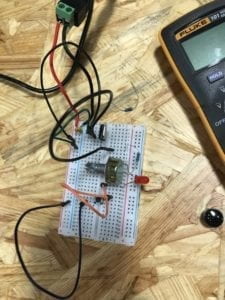
Multimeter: Measures voltage, current, and resistance. We used it in order to find the correct resistor for each circuit.

Push-Button Switch: Gives interactor the power to choose when to let the current flow.

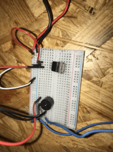
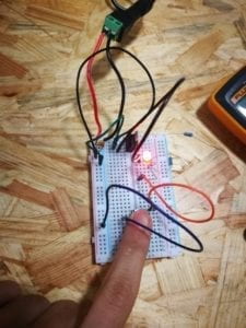
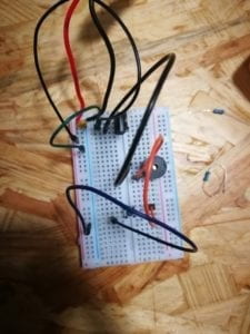
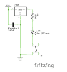
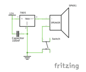
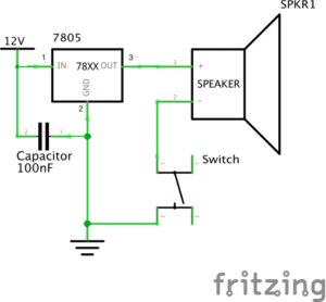
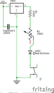
Circuit 1: Door Bell
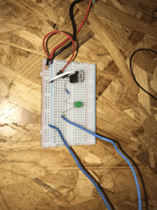
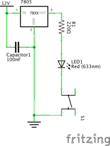
Circuit 2: Lamp
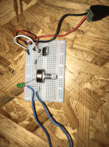
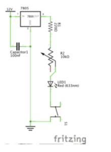
Circuit 3: Dimmable Lamp
Building Process:

Soldering:

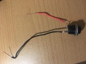
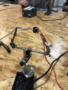
The process of soldering the two wires to the arcade button was a very rewarding and exciting experience. It was difficult to maneuver the positioning of the soldering iron with the wires to correctly connect them to the arcade button but with great teammate coordination, we were able to quickly complete the challenge.

-Circuit 1:

Building the first circuit was the most difficult as we had to learn how to work with the layout of the breadboard. We encountered problems because we were not familiar with the function of each piece, but once we had referred to the recitation notes, we were able to identify each piece in order to correctly place it in the breadboard. Once we had identified all the pieces and placed them in the correct circuit, we ran into another issue: the buzzer would not buzz. We then contacted the teaching fellows for assistance as our circuit was entirely correct but would not work. After switching out some of the pieces to make sure they were not causing the circuit to fail, the buzzer then worked! 

-Circuit 2:

Building the second circuit proved to be a lot smoother as we were more familiar with each piece’s function in the circuit as well as the layout of the breadboard. The only difference between circuit 1 and circuit 2 is that we had to replace the buzzer with an LED and we also had to add a resistor to tone down the voltage in order that the LED does not overheat. Because we could reuse a lot of the previous circuit, we did not run into the same equipment and layout issues as the previous circuit.

Circuit 3:

We also ran into similar problems with the last circuit. It proved to be more difficult than circuit 2, but easier than the first. The difference between circuit 2 and 3 is that we simply had to add the 10K ohm variable resistor so that we could adjust the brightness of the LED to our desire. Once we had added this resistor, the circuit ran into a problem as the LED would not turn on. So once again we asked the teaching fellow to assist us with the issue as we believed the layout of our circuit was correct. The teaching fellow then checked all parts of our circuit and it seemed to be correct, so then we deduced that the problem again lied in the reliability of the materials in our circuit. So then we arranged a few of the wires and replaced the 10k ohm variable resistor and the circuit started working! Once the circuit functioned we were able to turn the LED on as well as adjust the brightness.

Things I Learned:

During the process of building these first few circuits, I learned quite a few important things about the design process. One is that in order to learn and to progress with the goal that you are trying to accomplish, you can’t see failure as a hindrance. It is in fact just as important as any success, and in fact probably even more important because our failures teach us lessons that allow us to continue progressing. There were a couple of issues in the design process as stated above, but the recognition and then resolution of these issues helped me and my partner learn a lot more than we would have otherwise.

Question 1:

I believe that every circuit created in this recitation utilized some form of interaction. As stated in, The Art of Interactive Design, interaction is not a black and white scenario, but rather a continuous issue with many degrees. Interaction can be defined as a cyclical process where one actor performs one task, and another reacts, which then in response the original actor responds again. This is true within all of our circuits as they required our own participation as well as the circuits’ participation in order to perform the correct tasks. We interacted with circuit one by turning on the buzzer with the arcade switch, we interacted with circuit two by turning on the LED, and we also interacted with circuit three by adjusting the variable resistor in order to control the brightness of the LED. In all of these scenarios, my partner and I interacted with the circuit, and in response, the circuit provided us with a physical output in which we then reacted to. I also believe the design process itself is very interactive, as we design the circuit, and it then responds to us by performing the desired output or not.  In turn, we either enjoy our success or use the lack of output to continue to manipulate the circuit.

Question 2:

I believe that art is any kind of physical manifestation that is able to draw emotion from us. So from my personal definition of art, interaction design and physical computing are most definitely mediums that can be used to create interactive art. For example, The EyeWriter, mentioned in Zach Lieberman: Interactive Art, is a type of wearable technology that allows someone to draw digital images with the movement of their eyes. This technology is a form of interactive art because it allowed a paralyzed graffiti artist to continue his passion even if he no longer had control of the rest of his body. Art is simply a manifestation that permits us to think and feel and if that art also happens to be interactive, then I believe it has an even greater ability to draw us in and provide us with personal meaning. So because the EyeWriter allowed someone to pursue their passions that would have rather been hindered, of course, we can connect the disciplines of computing and design to interactive art.
Bing Chen Rec 1

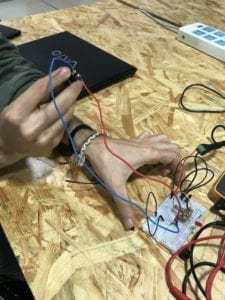
The circuit building process was relatively easy and completing the circuits gave me a sense of satisfaction because they all worked on the first try. My first time soldering was also quite interesting. I had always been a software kind of person so being able to make something with my own hands was satisfying to me. 

Regarding the components of the circuits and their purposes:

The 12V is the source of the power, which in this case was connected to the outlets. The variable resistor allows for the electricity to be adjusted, therefore allowing for the control of the brightness of the LED. The switch is a sensor that, when pressed, allows the LED to turn on. The LED is an actuator which converts electrical energy into light energy. The 220ohm resistor is used to control the flow of energy from the source so the LED doesn’t burst since the LED can only take 3V and the source provides 12V. The voltage regulator generates a fixed voltage output from the input of 12V. Capacitors store energy that passes through them until something lets it out. Something being the switch/button. In this case, the capacitor stores the leftover energy from the source and releases to ground. The speaker is an output device which produces sound when electricity enters it.

Question 1: I think the circuits I built with my partner include interactivity because it requires an action and reaction from two parties. The human who presses the button or rotates the variable resistor initiates the action, and the circuit reacts with the speaker and the LED light. 

Question 2: Art is something an artist creates by bringing to life what is floating around in their heads. Art doesn’t have to be stationary. Therefore any interactive design that is the product of an artist’s vision can be considered art. This form of art can even be considered a completely different form: a form which allows interaction between the art and the viewer. It changes the interactivity from the art being the viewed and the person being the viewer to an active relationship between two “interactors.” 

cof
cof

Documentation on soldering and electronics


The recitation last week mainly focuses on a number of basic electronic operations, soldering and configuring some circuits.

The process of soldering is pretty simple. After heating up the soldering iron, put the solder at the tip of the iron to let it melt, before putting the iron on the joint. After the spot is also heated up, apply solder onto somewhere near the joint and wait for it to melt. When the work is done, clean the tip. Though I have played around with it before, it seems my procedures were totally wrong. When I was soldering, I have been skipping the step on tinning the tip. What’s more, I have also been applying the solder right onto the joint or even the soldering tip. But finally, my partner and I have got the wires soldered securely soldered to the button. We even soldered to jump wires together.

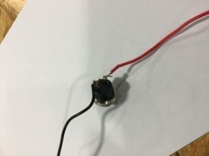
The button soldered to wires
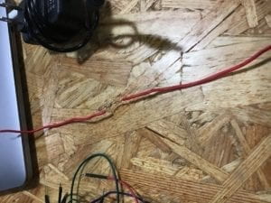
Two wires soldered together

Building the circuit was not complicated. Though when building the first circuit, we have encountered difficulties in reading the diagram, as the capacitator was a bit annoying. Therefore, we were confused about which socket should the wires and switches be connecting to. Another problem was the direction of the switches. We weren’t able to control the on and off of light using the switch, because we weren’t clear of the direction of the switch. After checking the information about the direction in the button, we made it work. But afterwards, we were able to get the first and second circuits working pretty quickly. The third circuit, however, involves more electrical components, so we were a little hesitated in wiring up. And my partner was not very familiar with the breadboard so that he almost connected two pins of an electronic component to the same row of the breadboard. After correcting his tiny mistake, we got our last circuit working as well. During the rest of the time, we used the potentiometer to make the tone of the speaker change while turning the potentiometer.

The brief description for the electronic components involved are down below:

BreakBoard: the board that has built-in wires, through which different electronic components can be connected more easily 

Voltage Regulator: adjust the voltage flowing into the circuit

Speaker: a buzzer that can make noisy sounds

Push-Button switch: used to turn the circuit on and off

Arcade Button: works the same as the Push-Button switch, but there are less pins to connect

Capacitor: store electricity inside, which would feed back to the circuit

Resistor: to reduce the current in the circuit and prevent the components from burning out

LED: light up when connected in a circuit

Variable Resistor: a resistor that can change its ohms

12 volts power supply: the power for all components in the circuit

In general, technically speaking, the recitation last week wasn’t very complicated. The difficulties we encountered mostly resulted from our lacking dexterity.

Based on The Art of Interactivity, our circuits have very limited interactivity. The only possible interaction was pushing the switch and have the light lights up or the speaker makes a sound. It is almost in the same circumstances as opening the door of the fridge when the light in the fridge lights up, or a person avoids the branches falling from a tree.

When it comes to the relationship between physical computing and interactive design, physical computing acts as the empowerment of the interactive design idea in the artists’ mind. And in the process, the physical computing itself is only a tool and should be made accessible, in order to have the artist focus on creating completely.

Week 1: Recitation Documentation –Zhiqiu Wang

Week 1: Recitation Documentation – Young

Recitation 1: Electronics and Soldering

Instructor: Young

Partner: Kaycee Chen

Materials Used in Circuits:

  • Breadboard – a device used for carrying and  connecting different materials 
  • LM7805 Voltage Regulator – the components used to maintain voltage output 
  • Buzzer – the out put, beep when working
  • Push-Button Switch – the device used to control the current
  • Arcade Button – another device used to control electrical flow through the circuit
  • 220 ohm Resistor – used to limi the voltage that flows in the circuit 
  • LED – out put, light up when electricity flows through
  • 100 nF (0.1uF) Capacitor – used to protect the circuit 
  • 10K ohm Variable Resistor (Potentiometer) – used to control the voltage that flows to the LED so as to control the brightness of the LED
  • 12 volt power supply – supply the circuit
  • Multimeter – can be used to test different information of different components
  • Several Jumper Cables (Hook-up Wires) –used to connect different components

Circuit 1: Lamp

Components used:  Breadboard, LM7805 Voltage Regulator, Buzzer, Push Button Switch/Arcade Button, 100 nF (0.1uF) Capacitor, 12 volt power supply, Barrel Jack

This small model is the first project that I have ever completed. Though it is very simple, it helps me to get to know about how do different components works together and function properly. Our group actually met with several obstacles at first, the LED didn’t light up after several attempts. After turn to Instructor Young for help, he examine all the components one by one and told us there is something wrong with the breadboard. So we changed a new breadboard and eventually saw the light given out from the LED. The second time we rearrange our jumper cables in a more organized way because Instructor Young told us it will be easier to debug in this way and we finished it much faster than we did it the first time.

Circuit 2: Door Bell

Components used: Breadboard, LM7805 Voltage Regulator, Buzzer, Push-Button Switch/Arcade Button, 100 nF (0.1uF) Capacitor, 12 volt power supply, Barrel Jack, 220 ohm Resistor, LED

With the experience of the first circuit assembling, my partner and I made the second circuit much faster. However, the Buzzer didn’t beep no matter how we test it. We turn to Instructor Young again and after checking our circuit he told us to pay attention to the direction of the switch. We found it very tricky but there is still tiny difference in it so we rearrange it and succeeded. 

Circuit 3: Dimmable Lamp

Components used: Breadboard, LM7805 Voltage Regulator, Buzzer, Push-Button Switch/Arcade Button, 100 nF (0.1uF) Capacitor, 12 volt power supply, Barrel Jack, 10K ohm Variable Resistor (Potentiometer), LED 

After succeeded twice, we finished this one quickly and successfully. It is really proud to see the brightness of the LED being manipulated by us.

Since I have experience of connecting jumper cable in a competition I took part in during my high school, it wasn’t a difficulty for me. I finished efficiently and helped my partner.

Question 1:

The Lamp light up, the buzzer beeps, the brightness of the LED changed when we press the button or turn the Variable Resistor. It is a kind of interaction between the circuit that we built and us.

Question 2:

I think more controllable components or sensors that will respond to motion, heat etc. can be used to create the interaction Design and Physical Computing because interaction means the project must interact with human beings so these components are very necessary to a successful Interaction art.

Documentation Week 1 Yixuan Liu (Marcela)

During the first recitation, our main task was to have a basic understanding of the commonly used components, and after that, we used these components to build three simple circuits to better absorb the materials that we have learned from the class.

Here are the components me and my partner used for building circuits:

  • Breadboard
  • LM7805 Voltage Regulator
  • Buzzer
  • Push-Button Switch
  • Arcade Button
  • 220-ohm Resistor
  • LED
  • 100 nF (0.1uF) Capacitor
  • 10K ohm Variable Resistor (Potentiometer)
  • 12-volt power supply
  • Barrel Jack
  • Multimeter
  • Several Jumper Cables (Hook-up Wires)

For this exercise, my original assumption was that this would be an introduction based recitation. I hoped that I could have a general idea of my class material this semester and be more prepared for this class. To be honest, after seeing the schematics of the circuits, I became more confident about what I was going to do because, from the diagrams, those circuits looked simple and clear.

Circuit 1

However, once I started, I realized the complexity of this exercise which was beyond my expectation. I and my partner started building the first circuit by connecting the switch with a resistor on the breadboard. After I plugged three wires into the breadboard, I immediately realized that doing the actual circuit was way complex than understandings the schematics. My first experiment, of course, failed because of my inaccurate understandings of my components. I also figured out the breadboard was the biggest problem. I did not understand how the breadboard functioned or what should I do to connect components correctly on the breadboard. In order to solve the problem, me and my partner asked the recitation instructor for detail explanation. Professor Young brought us the special breadboard with the transparent back from which we could be able to see the inside construction of the breadboard. After figuring out that we connected the negative part to the positive of the power and other several similar misconnecting mistakes, we quickly adjusted the circuit and heard the buzzer rang.

Circuit 2 & 3

For the second circuit, me and my partner actually used a shorter time than the first one took. However, this did not mean we make the LED light work successfully. For this time, we had a problem with the switch. No matter how many times we pressed the switch, the light just kept lightning all the time. It seemed like the switch became a hook-up wire and had no function at all. We had to ask for help again for this weird situation because we were not sure whether the switch was broken or we did something incorrectly. After checking the circuit with Professor Young, we found that we should connect the different sides of the switch for the positive and negative directions, otherwise it became a part of the hook-up wire.

As for the soldering stations, we did pretty well and got our new switch quickly after the instructor explained everything. After all the mistakes that we made before, the third circuit finally functioned well.

From all these processes of building circuits, I personally realize that how important to get a thorough understanding of the inside construction of my component. The case of the breadboard tells me that I should never make a naive assumption for an experiment without actually working on it. Besides, it also teaches me that in the future learning process, I should always be modest and ask for help.

Questions:

  1. I do feel the interactivity during building the circuits. From the reading we had this week, I learn that interactivity is absolutely more than just touching or hearing, but more, it should let people who interact with have the process of communication with the circuit. After lighting the LED, I felt that I could better understand the flow of the electricity and somehow I did not take the shining light for granted, instead, every time I saw a light, I unconsciously went through the process in the lab again. This experiment makes me more aware of my surroundings, and this is already interactive enough for me.
  2. From my point of view, after watching Zack Lieberman’s video, interactive art is trying to build a connection between people’s spiritual world and our physical world. Usually, how we use our biological sensors to interact with the outside world is quite invisible. By making this mutual communication process more visible and more influential is what physical computing can achieve. However, physical computing alone cannot become the art, but how we make use of the technology and how we interpret the statistical outcomes from technologies that resign endow physical computing deeper meaning. Hence, combining both physical and spiritual approaches, interactive art is making our inside world more visible.