Interaction Lab Recitation Documentation #1 (Guangbo Niu)

Circuit 1: Door Bell

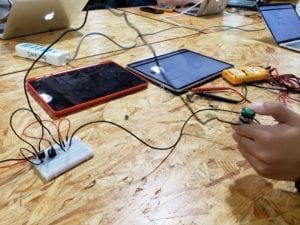
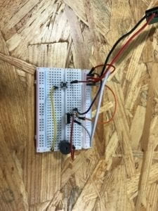
doorbell

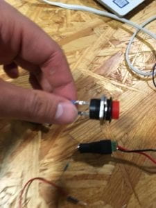
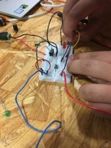
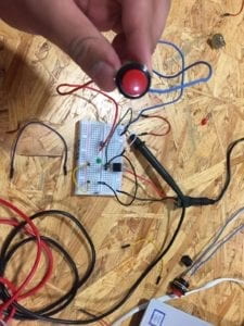
Circuit 1Circuit 2 w/ a big button

Components: 

  1. Capacitor, stores electricity.
  2. Voltage Regulator, stabilizes the voltage at a constant level.
  3. Push Button (Switch), switches between an open circuit and a closed circuit.
  4. Speaker, makes sound.
  5. Power (12V) , provides DC electricity power.
  6. Ground, prevents electric leakage from hurting human body.
  7. Jumper Cable, connects components and carries electricity.

It took us roughly an hour to figure out how to make it work. Firstly we had no idea how to use a breadboard until one of the fellows told us that the horizontal wholes on the same half are connected while the vertical ones are not. We also learned that the vertical wholes at the two sides of the board should be connected to power and ground lines.

We then came into a problem about the switch. The switch has four legs but we did not know which two to connect. We again consulted one of the fellows and learned that we should include only two legs in the circuit and connect them – leave the other two outside the circuit.

Lastly, we had trouble connecting to the ground. We found the circuit working well without connecting to the ground. And again, we asked one of the fellows to show us and we learned that we just simply had to connect the third leg of the voltage regulator to the minus side of the circuit, or negative electrode (I googled it).

What’s funny is, it is only after we completed the circuit when found out that our socket was broken…

Circuit 2: Lamplamp

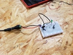
Circuit 2

  1. Resistor, provides resistance in the circuit to limit the current flow so that the load (door bell) works properly.
  2. Capacitor, stores electricity.
  3. Voltage Regulator, stabilizes the voltage at a constant level.
  4. Push Button (Switch), switches between an open circuit and a closed circuit.
  5. LED, gives out light.
  6. Power (12V) , provides DC electricity power.
  7. Ground, prevents electric leakage from hurting human body.
  8. Jumper Cable, connects components and carries electricity.

Circuit 2 was rather simple. We just had to replace the speaker with the LED and add a resistor next to it. We completed within 2 minutes, no problems at all.

Circuit 3: Dimmable Lamp

dimmable light

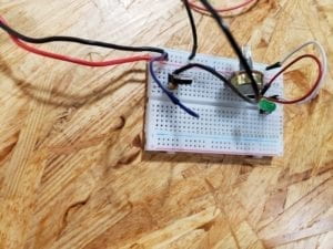
Circuit 3  

  1. Resistor, provides resistance in the circuit to limit the current flow so that the load (door bell) works properly.
  2. Capacitor, stores electricity.
  3. Voltage Regulator, stabilizes the voltage at a constant level.
  4. Push Button (Switch), switches between an open circuit and a closed circuit.
  5. LED, gives out light.
  6. Power (12V) , provides DC electricity power.
  7. Ground, prevents electric leakage from hurting human body.
  8. Jumper Cable, connects components and carries electricity.
  9. Variable Resistor / Potentiometer, varies its own resistance so as to varies current flow in the circuit, in order to dim the light.

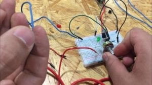
Well… We thought it would be easy if we just had to include a variable resistor next to the LED. But when we connected its two legs with the circuit and span its dial, the LED did not dim. And shortly after that, we recalled our high school Physics class and remembered that if a variable resistor was connected with its legs on the two sides, it would become a constant resistor. That is, we had to connect its middle leg to the resistor and another to LED, left the other leg disconnected.

Question 1:

After reading The Art of Interactive Design, in what way do you think that the circuits you built today include interactivity? Please explain your answer.

I think our circuits include interactivity because when we switch it on, it listens(receiving an input), thinks (processing the input), and speaks (producing output). At the same time, I speak (giving an input), think (imagining what would happen), and listen (literally listen to the doorbell, e.g.) Although I suppose the author of that reading would deem that kind of interaction as silly, I do believe the circuits interacted with me in terms of input, processing and output.

Question 2:

How can Interaction Design and Physical Computing be used to create Interactive Art? You can reference Zack Lieberman’s video or any other artist that you know .

Interaction Design and Physical Computing can be used to detect and record physical movements, gestures, and other analog signals made by either human or something else. For example, the eyewriter presented in the video detects eyeball movements. Those inputs can then be transformed to digital records, just like the eyeball movements being transformed into shapes and images. All these processes involves interactivity and eventually create art works, hence Interactive Art.

Recitation 1: Electronics and Soldering (Madeline Shedd)

Recitation 1: Electronics and Soldering

February 15th, 2019

Partner: Henry S

Goal:

This weeks recitation focused on learning the basics of circuits and soldering by completing a few simple circuits based on a schematic.

Materials:

  • Breadboard: the base of the circuit, it allows for power to flow through a series of connections between different parts of a circuit
  • LM7805 Voltage Regulator: converts 12V to 5V, a voltage the buzzer can handle
  • Buzzer: outputs a sound when supplied with the correct amount of power
  • Push-Button Switch: opens and closes the circuit, lets electricity flow when wanted
  • Arcade Button: the same concept as the switch, depending on the user it allows electricity to flow when pushed down
  • 220-ohm Resistor: adjusts the resistance of the electricity so the correct amount of power flows through the circuit
  • LED: light-emitting diode, the “lamp” of this exercise
  • 100 nF (0.1uF) Capacitor: used to stabilize the flow of electricity by storing power while the circuit is connected to power and releases it once power is disconnected
  • 10K ohm Variable Resistor (Potentiometer): adjusts the amount of resistance so more or less voltage is let through
  • 12-volt power supply: provides power to the circuit
  • Barrel Jack: the connection that supplies the power
  • Assorted Jumper Cables: connects the components of the circuit together

Circuit 1: Doorbell

Circuit 1 Diagram

Circuit 1

We didn’t have too much difficulty piecing everything together on this first circuit. Once we were able to understand the schematic, we thought we had everything in the correct place. But we were having problems making the buzzer make a sound. We rechecked connecting wires and moved the capacitor around and still no sound. We then decided to ask for a little help because we didn’t know what else could be wrong. After getting help, we exchanged the voltage regulator and still no sound, switched the buzzer and yet again got no sound. So we got another voltage regulator and tried one last time and the circuit worked perfectly.

Circuit 2: Lamp

Circuit 2 Diagram

Circuit 2

Creating the circuit for this one was much easier than the first one since we didn’t have to deal with faulty parts this time. We basically kept everything the same except for removing the buzzer and adding in the resistor and LED. After doing this, the light successfully turned on our first try.

Circuit 3: Dimmable Lamp

Circuit 3 Diagram

Circuit 3

This circuit was also pretty easy as well. We at first mixed up the wire positions for the potentiometer, but after rechecking the schematic we were able to figure it out. We also added on the arcade button at this stage, it was a very simple exchange. Once everything was connected, the circuit worked as planned.

Question 1:

I do believe these circuits have some level of interactivity. We can see this because we have to interact with it, push a button or twist a potentiometer, and then getting a result from that interaction, the light turning on or a buzzer going off. But this interaction stops with this result. The text presents the definition, “interaction: a cyclic process in which two actors alternately listen, think, and speak”. The circuit listens to us by responding to our actions, but it’s not like the light will speak back to us or have some effect that prompts us to do something in return. Because of this, the circuits can be interacted with but to a low level of interactivity.

Question 2:

By combining interaction design and physical computing, you’re just opening a new door for self-expression another medium. Through this self-expression, you can connect with others who view your work. With interactive art, you can connect with your audience in a much more intimate way. In Zack Lieberman’s video, not only did he intrigue his audience greatly, the got up close and interacted with his work which probably left a bigger imprint on them rather than if they had just observed. With this extra ability to be able to convey more and to have your audience literally experience a piece of artwork is, in my opinion, more memorable and touching than simply just viewing a painting.

Santiago Salem- Week 1 Documentation

Ingredients

  • 1 * Breadboard: Basic device to connect all components
  • 1 * LM7805 Voltage Regulator: To regulate how much electricity is being used
  • 1 * Buzzer:Device that makes the sound
  • 1 * Push-Button Switch: Stops or activates the flow of electricity
  • 1 * Arcade Button: controller of electricity
  • 1 * 220 ohm Resistor: reduces the voltage
  • 1 * LED: The light
  • 1 * 100 nF (0.1uF) Capacitor: energy storage
  • 1 * 10K ohm Variable Resistor (Potentiometer): voltage divider
  • 1 * 12 volt power supply:Where the power comes from
  • 1 * Barrel Jack: The plug
  • 1 * Multimeter: measures the voltage
  • Several Jumper Cables (Hook-up Wires): main source of transportation for electricity (they connect to the breadboard and other components to carry the energy)

Partner: Andres Malaga

Before starting to assemble the circuits we had to attend a soldering workshop. In that workshop we learned how to melt metal for the purpose of sticking things together. For example, we had to stick some cables to a button that would then serve as a switch for circuit 2

Circuit 1) The Door Bell

The first circuit  was the most complicated to assemble, since we had to experiment and understand all the parts that the diagram illustrated. The purpose of this circuit is to create a sound through a small bell when pushing the switch. Although the diagram and the instructions are clear, it was difficult for us to understand how the electricity flows inside the breadboard. The second problem was that I accidentally touched the LM7805 Voltage Regulator and burned my finger. What I did not know is that this regulator reduces the electricity from 12v to 5v and when doing that, it overheats a lot.


Circuit 2) The lamp

Assembling this circuit was much easier and safer. After learning how each component works we where able to assemble this circuit much faster. The only thing we found challenging was that sometimes we connected to many cables in only one line of the motherboard so we often got confused. During this circuit we used the arcade button that we assemble during the first workshop to activate the LED. 


Circuit 3) Dimmable Lamp

The process to assemble this circuit was similar to that of the second circuit. Although I almost forgot to put a resistor because I thought the LM7805 Voltage Regulator was gonna reduce the voltage but luckily someone helped us before the LED was gonna burn. The other thing I learned is that we still had to push the arcade bottom to turn on the LED as I thought that the potentiometer had this purpose.  

Question 1) 

First I would like to address the formal definition of interaction given by the author of  The Art of Interactive Design, Interaction: a cyclic process in which two actors alternately listen, think, and speak”. Although the authors uses this definition more as a metaphor, for this circuit the interaction we encounter among the components was a more responsive reaction to how each ingredient is dependent on the other. For instance, how pushing the switch will ultimately end up on emitting a sound through the buzzer. Although in the case of the circuit all of this is possible through and only through the use of electricity. Therefore, I believe that in order for us to conceive interaction there must be a key factor that all the components share, so in the case of all this circuit the main factor was electricity. Same with humans, there must be a key factor sending signals in order for us to speak, listen and hear. 

Question 2)

From my perspective I had never appreciated how Interaction Design and Physical Computing had the ability to create Interactive Art. Before I only saw both for the purpose of developing technology. But now that I think about it, the school last semester took us to Shenzhen for a technology convention, were I had the opportunity to admire this type of art (without knowing where and how it came from). For example: there was a box where if you came closer it showed you different type of images (this was possible through detectors that where activated though movement). I just find it extremely cool that art can also be responsive to interaction. Not only it is fun and stunning but it also connects the audience closer to art.

Caren Yim – Week 1 : Electronics and Soldering

Introduction: The purpose of this week’s lab was to understand the basics of circuits through the completion of three circuits and to learn how to solder.


Circuit 1: Doorbell

Components:

  • LM7805 Voltage Regulator: maintain a constant voltage level for the circuit
  • Breadboard: base that allows for circuit connections, usually used for prototyping stage 
  • Push button Switch: interrupts the flow of current going through the circuit which allows the speaker to turn off and on
  • Speaker: creates sound, in terms of the circuit it allowed us to know if our circuit was working
  • 100 nF Capacitor: stores electrical energy and allowed the LM7805 Voltage regulator to work
  • Wires: allow current to flow from one location to another
  • 12 Volt Power supply: supply power to the breadboard

Process: In Circuit 1, my partner and I had to familiarize ourselves with the symbols and their corresponding components. When we first started, we started by inserting the speaker on the breadboard and attempted to work around that. However, we were advised that to start, it would be best to insert the 12 volts and the ground first. This was helpful because it built our understanding of ground and volts. The first problem we encountered was when we placed the capacitor into the power bus and the ground bus. We were told that instead, we can attach it to the same row of the regulator since the rows were already connected to both the ground and 12 volts. In the end, we were successfully able to get the circuit working.


Circuit 2:  Lamp

Components:

  • LM7805 Voltage Regulator: maintain a constant voltage level for the circuit
  • Breadboard: base that allows for circuit connections
  • Push Button Switch: interrupts the flow of current going through the circuit which allows the speaker to turn off and on
  • LED: light emitting diode, emits light
  • 220-Ohm Resistor: prevent too much current from passing through to the LED, control current flow
  • Capacitor: stores electrical energy
  • Wires: allow current to flow from one location to another
  • 12 Volt Power supply: supply power to the breadboard

Process: The first step in this circuit was making sure the resistor was at 220 ohm, to do this we used a multimeter. Since half of the setup was identical to circuit 1’s setup, we only took out the parts that weren’t needed for the second circuit and worked from there. An error that was made in this process was not considering the polarity of the LED light. When we completed the schematic we were not sure why the LED wasn’t lighting up, we asked for guidance and were told it was because the polarity of the LED was inserted wrong. After fixing this, the LED light lit up when the switch was pressed. We were successful in creating circuit 2.


Circuit 3: Dimmable Lamp

Components:

  • LM7805 Voltage Regulator: maintain a constant voltage level for the circuit
  • Breadboard: base that allows for circuit connections
  • Push button Switch: interrupts the flow of current going through the circuit which allows the speaker to turn off and on
  • LED: light emitting diode, emits light
  • Resistor: prevent too much current from passing through to the LED, control current flow
  • Capacitor: stores electrical energy
  • Wires: allow current to flow from one location to another
  • 220-Ohm Resistor: prevent too much current from passing through to the LED, control current flow
  • 12 Volt Power supply: supply power to the breadboard
  • Variable Resistor: allows the current resistance to be adjusted

Process:  The materials needed for this circuit was almost identical to the second circuit except a variable resistor was added. This circuit was easy to build because only the variable resistor needed to be added. We were a little troubled at first due to not being able to figure out which part of the variable resistor corresponded with the ones in the diagram provided. However, we were able to figure it out and in the end, successfully completed the circuit.


Questions: 

1.  In the reading, the author defines interaction as “a cyclic process in which two actors alternately listen, think, and speak”. Based off of this definition the circuits that were built today showed a level of interactivity. This is because each component within each circuit in a sense was “listening” to the parts before them for instructions and then “thought” about its role and then by creating a reaction they “spoke”. This process is repeated once an individual gives the circuit the signal to start. Even the process of building circuits was interactive, we inputted the work and as a result, the circuits responded back to us by having the LED light up or even the speaker making a sound when the switch was pressed. These were all responses to an action and that is what interactivity is.

2. Interaction Design and Physical Computing can be used to create interactive art in many ways. An example of the lengths both these combined can do to contribute to the interactive art realm is a project inspired by Tony Quan, a paralyzed graffiti artist. By studying human behavior and combining that with computing it allowed for the production of interactive art. The eye-tracking art was able to move in conjunction with a part of the human body. Interactive art gives life to a new form of creativity and has endless possibilities.

Interaction Lab – Recitation 01 – (Cossovich)

Components:

Voltage Regulator- A system/component which regulates the amount of voltage it lets pass through. This is often used if your power source is greater than the component which you need to power. The regulator acts like a diffuser of energy. This component was included in all of the circuits as the components we needed to power (speaker, LEDs) required a smaller amount of voltage as given by our power supply.

Capacitor – A two-terminal electronic component which is used to store energy in an electric field. Like the voltage regulator, the capacitor was used in all the circuits to help regulate the flow of energy and to store extra energy that may have been flowing through the circuit.

Switch – the switch is used to make or break the electric flow through a circuit, or allow things to flow to a certain element when the switch is on. This was used in all the circuits as there were components (speaker, LED) that we only wanted to be powered when the switch was on.

Speaker – Emits a sound

220 Ohm Resistor – Two-terminal electronic component used to control the flow of a current. This was used in all circuits to help regulate the flow of currents.

Light-Emitting Diode (LED)- A type of diode (a two-terminal component with a polarized direction of energy) which emits light when energy flows through it.

Variable Resistor: A resistor (component that controls flow of electricity), which allows you to resist a variable amount of electricity flow through (eg., more or less energy can flow based on position). This was used in circuit 3 as we wanted to create a dimmable lamp, and hence needed a component that could let a variable amount of energy through at a given time based on analog input.

Circuit 1 – Door Bell

At first, my partner and I didn’t know exactly how to set up the circuit on the breadboard, and while we thought we had everything connected, we did not. My main confusion was trying to figure out how to create the ground, along with being able to translate the diagram of the circuit onto the breadboard. Another struggle we faced was connecting the voltage regulator as we did not at first understand that the three different pins had to be connected to different components, but after Eric told us this, we were able to complete the circuit (and we were very excited when we heard the speaker).

Picture of Circuit 1

Circuit 2 – Lamp

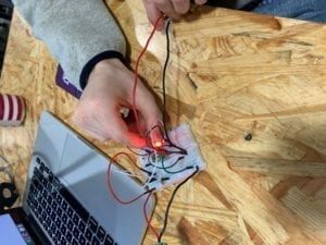
After assembling the first circuit, my partner and I had a better understanding of how things should be connected. However, we did not figure out at first that the LED was polarized, but then I figured that the different wire lengths could mean something. As with the first circuit, it took us some time and tinkering to get everything in the right place, and because the breadboard is so small, we couldn’t see that one of our wires was a row away from being able to connect with the voltage regulator. Also, in the image you can see that we forgot to add the capacitor into our circuit, but our circuit was still powered without it. Though I could imagine that if we left the circuit powered for an extensive period of time that something would go wrong.

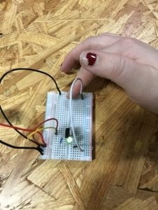
Circuit 2, with switch being pushed and LED on

Circuit 3 – Dimmable Lamp

This circuit was the most challenging, and because of that, I decided to first build it with the smaller switch (instead of the arcade button). Like the voltage regulator in the first circuit, my partner and I struggled with the variable resistor at first, due to the different pins (and trying to see which row the pins were in amongst our tangle of jumper wires).

IMG_5696  <– video of the completed circuit

Question 1:

I believe that all the circuits we built today can be considered as interactive, but I would argue to say that the “Dimmable Lamp” was the most interactive circuit. As mentioned in The Art of Interactive Design, certain things contain certain degrees of interactivity. Due to the fact that the variable resistor not only allowed us to power an LED but to also change the brightness of the LED, this circuit contains more potential for interaction. Along with this, all the circuits are interactive because they require more than one actor. One of the actors is the circuit itself, and the other actor is the thing which pushes the button. If the circuits did not have the switch/button, they would not be interactive because the LEDs and speaker would constantly be powered without any other actor helping them to do so.

Question 2:

Interaction design and physical computing work together to make innovative forms of art that are more accessible, and are completely different than types of traditional art. With interaction design, we see art forms that rely on a user input to be made, and hence gives them another dimension. As we see with Daniel Rozin’s mirrors, his art comes alive once it is interacted with. While his art was based on principles of interaction design, the software and wiring behind the art is a type of physical computing. Therefore, I believe that art is now moving to include more digital and electronic components compared to it’s past definitions.