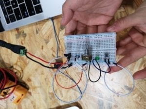
Recitation 2: Arduino Basics(Alex Wang)

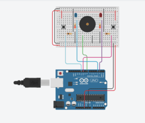
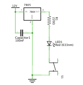
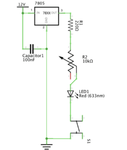
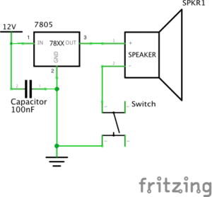
In week 2 recitation we are tasked with building basic circuits just like week 1 recitation, but this time we included the use of Arduino code. Specifically an automated fading led, an music player, and a led racing game with the optional improvement for adding multiplayer.(Schematics below)
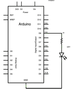
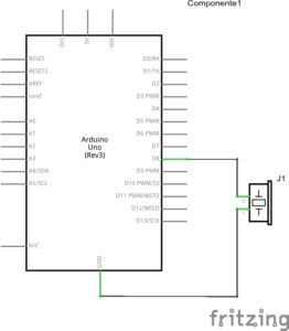
Process:

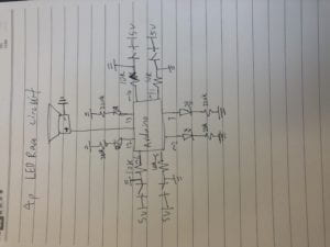
For this weeks recitation I haven’t ran into any problems, we built the circuits and ran the code, everything went smoothly. We are also extra careful during the process and made sure no connection was loose, unplug power source when editing circuit, etc. I was able to complete the optional circuit fairly quickly too, we left our LED racing circuit as it is, and added another groups circuit to our initial circuit. instead of the pins assigned from the original code, I attached the buttons to `5 and `6 and the LEDs to 12 and 13 on the Arduino, and then modified the code to match the pin slots as well as adding win conditions and variables for the newly added player3 and player4(Hand Drawn diagram and video of working circuit below).
9

10

Modified code:

//led race game modified for 4 players
int buzzerPin = 8;
int button1 = 11;
int button2 = 10;
int button3 = 5;
int button4 = 6;
int led1 = 3;
int led2 = 2;
int led3 = 13;
int led4 = 12;

int goal = 10;
int buttonState1 = LOW;
int previousState1 = LOW;
int buttonState2 = LOW;
int previousState2 = LOW;
int buttonState3 = LOW;
int previousState3 = LOW;
int buttonState4 = LOW;
int previousState4 = LOW;

int counter1 = 0;
int counter2 = 0;
int counter3 = 0;
int counter4 = 0;
boolean winner1 = false;
boolean winner2 = false;
boolean winner3 = false;
boolean winner4 = false;

// the follow variables are long's because the time, measured in miliseconds,
// will quickly become a bigger number than can be stored in an int.
long time = 0; // the last time the output pin was toggled
long debounce = 200; // the debounce time, increase if the output flickers

void setup() {
// put your setup code here, to run once:
Serial.begin(9600);
pinMode(buzzerPin, OUTPUT);
pinMode(button1, INPUT);
pinMode(button2, INPUT);
pinMode(button3, INPUT);
pinMode(button4, INPUT);
pinMode(led1, OUTPUT);
pinMode(led2, OUTPUT);
pinMode(led3, OUTPUT);
pinMode(led4, OUTPUT);
Serial.println("******************* RACE THE LED *******************");
delay(1000);
Serial.println("READY");
delay(1000);
Serial.println("SET");
delay(1500);
Serial.println("GO!!!!!!!!!!!!!!!!");

}

void loop() {
// put your main code here, to run repeatedly:
buttonState1 = digitalRead(button1);
buttonState2 = digitalRead(button2);
buttonState3 = digitalRead(button3);
buttonState4 = digitalRead(button4);
//Serial.println(buttonState1);

//this checks the times player 01 has pressed the button
if (counter1 < goal && winner2 == false && winner3 == false && winner4 == false) {
if (buttonState1 != previousState1 && millis() - time > debounce) {
if (buttonState1 == HIGH) {
counter1++;
Serial.print("player 01: ");
Serial.println(counter1);
time = millis();
}
}
previousState1 = buttonState1;
if (counter1 == goal && winner2 == false && winner3 == false && winner4 == false) {
winner1 = true;
digitalWrite(led1, HIGH);
Serial.println("PLAYER 01 WINS");
playMelody();
}
}

//this checks the times player 02 has pressed the button

if (counter2 < goal && winner1 == false && winner3 == false && winner4 == false) {
if (buttonState2 != previousState2 && millis() - time > debounce) {
if (buttonState2 == HIGH) {
counter2++;
Serial.print("player 02: ");
Serial.println(counter2);
time = millis();
}
}
previousState2 = buttonState2;
if (counter2 == goal && winner2 == false && winner1 == false && winner3 == false && winner4 == false) {
winner2 = true;
digitalWrite(led2, HIGH);
Serial.println("PLAYER 02 WINS");
playMelody();
}
}

//for player 3
if (counter3 < goal && winner1 == false && winner3 == false && winner4 == false) {
if (buttonState3 != previousState3 && millis() - time > debounce) {
if (buttonState3 == HIGH) {
counter3++;
Serial.print("player 03: ");
Serial.println(counter3);
time = millis();
}
}
previousState3 = buttonState3;
if (counter3 == goal && winner3 == false && winner1 == false && winner2 == false && winner4 == false) {
winner3 = true;
digitalWrite(led3, HIGH);
Serial.println("PLAYER 03 WINS");
playMelody();
}
}
//for player 4
if (counter4 < goal && winner1 == false && winner3 == false && winner4 == false) {
if (buttonState4 != previousState4 && millis() - time > debounce) {
if (buttonState4 == HIGH) {
counter4++;
Serial.print("player 04: ");
Serial.println(counter4);
time = millis();
}
}
previousState4 = buttonState4;
if (counter4 == goal && winner4 == false && winner1 == false && winner3 == false && winner2 == false) {
winner4 = true;
digitalWrite(led4, HIGH);
Serial.println("PLAYER 04 WINS");
playMelody();
}
}

}

void playFreq(double freqHz, int durationMs) {
//Calculate the period in microseconds
int periodMicro = int((1 / freqHz) * 1000000);
int halfPeriod = periodMicro / 2;

//store start time
int startTime = millis();

//(millis() - startTime) is elapsed play time
while ((millis() - startTime) < durationMs) {
digitalWrite(buzzerPin, HIGH);
delayMicroseconds(halfPeriod);
digitalWrite(buzzerPin, LOW);
delayMicroseconds(halfPeriod);
}
}

void playMelody() {

playFreq(262, 100);
playFreq(294, 100);
playFreq(349, 100);
playFreq(294, 100);
playFreq(440, 200);
delay(100);
playFreq(440, 400);
playFreq(392, 400);
delay(300);
playFreq(262, 100);
playFreq(294, 100);
playFreq(349, 100);
playFreq(294, 100);
playFreq(392, 200);
delay(100);
playFreq(392, 400);
playFreq(349, 400);

}

Reflection:

I really liked this weeks recitation. Since I have previous experiences in coding, I was able to complete the tasks very smoothly. Learning form last weeks mistakes, I am now always extra careful during the construction to make sure that the connections are all secured, cause as the circuits that I am making gets more and more complex, it gets harder to keep track of every single thing, and as long as one part of the connection is not done properly, the whole thing stops working. I feel like building a circuit is very similar to coding, one part goes wrong and you have to spend a long time trying to find where the error is.

Documentation Questions:

Q1:Reflect how you use technology in your daily life and on the circuits you just built. Use the text Physical Computing and your own observations to define interaction.

I believe that technology plays a great role in my daily life, either for communication or transportation or even for entertainment. I guess for this weeks LED racing game, it would be for the entertainment for users. Just like how I would play video games on my computer. As for defining interaction, I agree with Chris Crawford on how the computers have similar phases of interaction just like humans: listening, thinking, and speaking. But unlike humans, computers use sensors to listen, CPU to think, and some kind of output to “speak” back to us.

Q2:If you have 100,000 LEDs of any brightness and color at your disposal, what would you make and where would you put it?

If I have 100,000 LEDs, I will probably create a huge art project with it. to build a huge screen of lights and display images through these LEDs.
Karen Zhang – Documentation – Recitation 1: Electronics & Soldering

For last week’s recitation, students were expected to build three different circuits and learn how to solder. Here is a list of components we used in the circuits.

Components :

Breadboard: it provides a base for making electronic connections

LM7805 Voltage Regulator: it is designed to automatically maintain a constant voltage level

Buzzer: when it is connected, it can make a buzzing noise

Button: it is used to interrupt or connect the flow of current through a circuit

220 ohm Resistor: it can add resistance to the circuit to decrease the voltage
LED: it lights when it is connected!

100 nF (0.1uF) Capacitor: used to stabilize and smooth the flow of electricity

Barrel Jack: it connects the power supply with the breadboard.

10K ohm Variable Resistor (Potentiometer): its resistance can change


Multimeter: it can measure electric current, voltage, and resistance. And we use it to measure the resistance.

Several Jumper Cables (Hook-up Wires): it is used to connect different electrical components.

Circuit 1

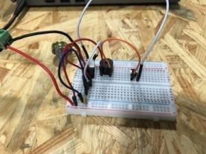
I think it takes me a long time to figure out how to build the first circuit. The first part we get confused is how to use the breadboard. After being taught by instructors, this problem was soon solved, and my partner and I started to build the circuit.
For Circuit 1, we connected all the necessary components, but the bell did not ring. We guessed that there was something wrong with the capacitor since that is the last part we put on the breadboard. By examing the circuit again, we found out that we did not need so many wires to connect, just directly connect the capacitor on the left side of the breadboard, the problem is solved! Also, the lesson I learned from this failure is that do not use so many wires! It could make your work more complicated and much harder to find out what was wrong.


Circuit 2

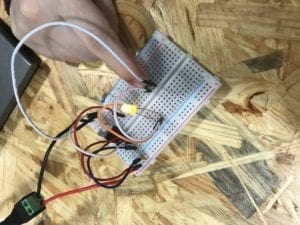
 Making the second circuit is much smoother than the first one. However, when I pressed the button, the lamp did not light. We could not find the reason why. After checking the circuit again and again, we believed that we perfectly connected each component. Then, another instructor pointed out our problem, why don’t you guys check the LED again? And we just realized we connected the LED is an opposite direction. The longer leg should be connected to the resister, and the shorter leg should be connected to the switch. 

Circuit 3

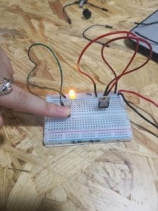
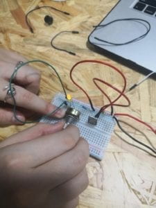
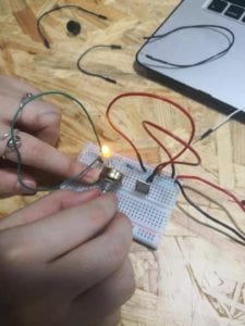
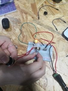
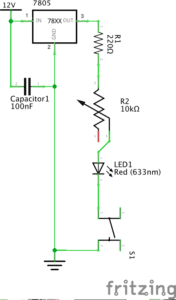
Based on the previous lessons we had, the third circuit is finished one time. We used the variable resistor to adjust the brightness of the light. 

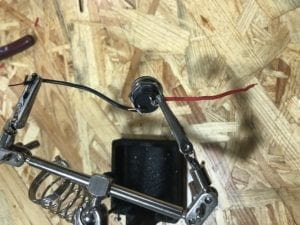
Then my partner and I went to soldering stations to learn how to solder. We need to connect two wires with the switch together. Tan the tip, then melt and put solder into the joint, the solar having a lower melting point than the adjoining metal. We waited for it to cool down, so the wires and switch could tightly connect. Overall, it is an easy task. However, it could be tricky at first to put the melting solar to the right position precisely at the joint.

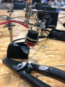
On the left of this picture, it is the new switch we made by soldering the wires

Answers to Questions

Question 1:
After reading The Art of Interactive Design, the circuits we built all include interactivity. In my opinion, there are two actors in the interaction. The circuits are built to illustrate the interactivity between what we built and us. It acts like communication that we have. As I press the button or turn the variable resistor, the lamp and bell respond to me. The ringing of the bell and the lighting of the lamp both show the interactivity.

Question 2:
From Zack Lieberman’s video, I think that adding physical computing technologies to art can actually make drawing more interesting and interactive. Lieberman presents three examples in the video and shows us how interactive art is created by computing and design. I am particularly interested in the third example. He used the simple eye-tracking system and allowed disabled artists to draw graffiti using their eyes. And it all relied on the technology(physical computing), which makes it all happen.

IL(Young) – Recitation1: Electronics & Soldering, Olivia Zhou

Materials and functions:

  • 1 * Breadboard      Provide a base for making electronic connections and aid in the prototyping of circuits.
  • 1 * LM7805 Voltage Regulator    Maintain a constant voltage level. Make the output voltage 5V for other components to work safely.
  • 1 * Buzzer      An audio signaling device.We can tell if the circuit works by listening to it.
  • 1 * Push-Button Switch      Be used to interrupt the flow of current through a circuit. We use it to control(turn on/off) the buzz and the LED.
  • 1 * Arcade Button     Be used to interrupt the flow of current through a circuit. We use it in soldering. Actually it’s an alternative of push-button switch.
  • 1 * 220 ohm Resistor      Resist the flow of electricity to control the flow of current. It protects the LED from burning out.
  • 1 * LED      A visible light source. We can tell if the circuit works by looking at it.
  • 1 * 100 nF (0.1uF) Capacitor      Store electricity while current is flowing into them, then release the energy when the incoming current is removed. (Question: I still don’t know why it is included in circuits and in parallel with other loads)
  • 1 * 10K ohm Variable Resistor (Potentiometer)      A resistor whose resistance can be adjusted. We use it to change the degree of LED brightness.
  • 1 * 12 volt power supply      Provide the power for other components to work. It( 12V DC) was translated from 220V AC and then to 5V DC.
  • 1 * Barrel Jack      It connects the power supply with the breadboard.
  • 1 * Multimeter      Be able to measure the electrical properties of voltage, current and resistance. They are useful for testing circuits and determine the cause of electrical problems within a circuit. We use it to measure the resistance to find a 220 ohm resistor out of others.
  • Several Jumper Cables (Hook-up Wires)      Be used to carry electricity from one point to another. We use it to connect different electrical components.

Tasks

  • Circuit 1

diagram

Picture of Door Bell

video

process    

 Actually, this was my first time to build a circuit, although I had previewed some readings, I still got confused at first. So did my partner Sarah. So she asked a teaching fellow for help. The fellow almost helped us through the whole course. The first problem we confronted is about  the resistors . We measured several resistors with the multimeter. But their resistance were all 10 ohm. At last we found one 220- ohm resistor with the help of the fellow.

  • Circuit 2

diagram

video

process

In this task, we added a new component: switch. But after we finished building the circuit and pressed the button on the switch, it didn’t work because the LED was always on. With the help of the teaching fellow we found out that we actually put the switch in the wrong place, so it was always connected. Later we put it across the middle line of the breadboard. 

  • Circuit 3

diagram

video

process

We built this circuit quite successfully and smoothly, just by adding a potentiometer on the basis of task two.

  • Soldering

picture

process

My partner Sarah tried to solder the Arcade Button with the red electric wire first, and the teaching fellow( another) emphasized that we should use the side of the tip of the iron instead of the very tip and scratch the soldering iron in the box when that part turns dim. But when I tired to solder the Arcade Button with the black electric wire, it still turned to be difficult to feed the melting roll of solder into the contact point. Anyway, I made it.

Answers to questions:

 1. In “The Art of Interactive Design”, the author generalizes the notion of the conversation as an interactive process to any human interaction and condensed it to three steps: listen, think, and speak (in turn). Academically, it’s input, process and output. From my perspective, the circuits we built do include interactivity because they can respond to our deeds like clicking the button of switch and changing the resistance of potentiometer by turning on and off the buzz/LED and changing the degree of LED brightness. But it’s also of low interactivity like the example of refrigerator light given by the author.

2. In Zach Lieberman’s video, the most impressive project for me is EyeWriter designed for paralyzed graffiti writer Tony. Their team created low-cost eye-tracking softwares and hardwares( connecting IR LEDs, micro CCD CAM, etc to sunglasses with copper wires and wire ties ), the result was quite pleasant that Tony could write graffiti and polish his works with his eyeballs, and his graffiti was even shadowed to the building.In my opinion, Interaction Design is the inner inspiration and Physical Computing is the technical basis for the design to be operated successfully. Interactive Art is created by the combination of the two.

Reference list:

Class 02 / Feb 14 Thu / Electricity, Electrical Components & Circuits

The Art of Interactive Design

Zach Lieberman’s video

Recitation 1. Electronics & Soldering by Frances (Fan Yuan)

Week 1: Recitation Documentation

Recitation 1: Electronics & Soldering

Instructor: Marcela

Circuit 1: Door Bell

Components:

  • Breadboard: This is where we plug in wires and connect all the components
  • LM7805 Voltage Regulator: It is used to maintain a constant voltage level
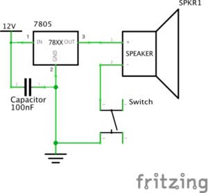
  • Buzzer: It is used as the speaker in the schematics, which will make sounds when the circuit is connected.
  • Push-Button Switch: To turn the speaker on and off.
  • 100 nF (0.1uF) Capacitor: It is parallel connected in the circuit. It blocks the direct current and let direct current to pass through the speaker, while it allows alternating current to pass and directly goes to the ground.
  • 12 volt power supply: Transfer 220V AC power and supply 12V power for the circuit.
  • Barrel Jack
  • Jumper Cables (Hook-up Wires)

Process:

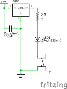
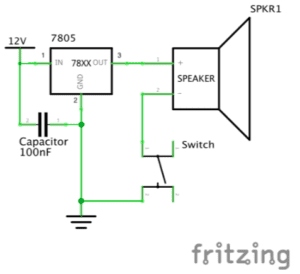
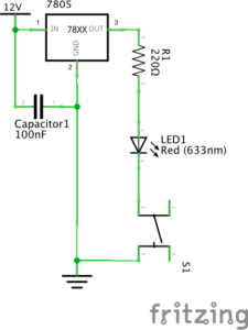
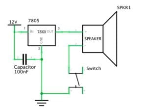
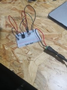
At first, it took us some time to figure out how to provide 12V power supply, as the power source part is not clearly shown on the schematics. We found out at last that we need to connect our circuit to the socket and the equipment we had will transfer the electricity to 12V DC. And then we spent some time to get familiar with the breadboard, as we can’t see which parts are connected inside the board. After knowing exactly how current flows inside the board, things got easier. One last thing that we had trouble with was the ground. There are three components that is connected to it: switch, capacitor and the “GND” of the voltage regulator, so we got a little confused but we solved the problem eventually.

Circuit 2: Lamp

Components:

Breadboard, LM7805 Voltage Regulator, Push-Button Switch, 100 nF (0.1uF) Capacitor, Jumper Cables (Hook-up Wires)

  • 220 ohm Resistor: It decreases the current magnitude and protects the LED from burning.
  • Multimeter: It is used to distinguish the 220 and 10K ohm Resistors.
  • LED

Process:

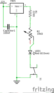
Building the second circuit was easier because we already had the first one. We didn’t have to build it from the start, but only needed to take off the speaker and replace it with the 220 ohm resistor and LED light.

Circuit 3: Dimmable Lamp

Components:

Breadboard, LM7805 Voltage Regulator, Push-Button Switch, 100 nF (0.1uF) Capacitor, Jumper Cables (Hook-up Wires), 220 ohm Resistor, LED

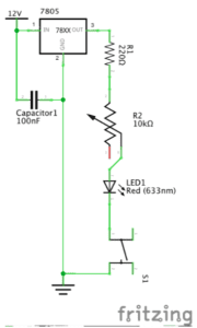
  • 10K ohm Variable Resistor (Potentiometer): By changing the resistance of it, we can change the LED’s brightness.
  • Arcade Button

Process:

For the third circuit, we also built it based on the second one we already had. We added the 10K ohm variable resistor between the 220 ohm resistor and LED. After that, we went to the soldering station and soldered wires to an arcade button to make it connectable to the breadboard. Then, we went back to use it to replace the push button. While as we removed our completed circuit too early, we had to reconnect it again. And this time we accidentally plugged in the LED in the wrong direction, and it didn’t light up. This is a problem that we should pay more attention to next time.

Reading responses:

Question 1:

The circuits we built are to some extent similar to the refrigerator example in the article. The circuit could be considered interactive, as it listens (to the pressing button), thinks (with current flowing through the circuit in a certain direction), and speaks (by making sounds or lighting up). However, I also agree with the author that it is low-level interactivity, that it does not contain much meaning or thoughts with such interaction.

Question 2:

Interactive art could be created when it involves more thoughts and communications back and forth. In one of the projects that we saw in class, a plant owns its Twitter account by using Arduino and sensors to sense its states and send tweets online. This is a good example of interactivity. And I think the more important part about Interactive Art is not merely reacting to commands, but delivering information or expressing feelings.

Recitation 1: Electronics & Soldering – By Skyler Liu

Solder an Arcade Button

Before we finished the circuit 1, we learned how to solder an arcade Button. We first cut a piece of wire in half and stripped one end of each half of the wire. Then we had the button fixed, and melted an end of a piece of metal wire, dripping the melting metal to the connecting hole of the button. At last, we needed to connect the exposed end of the wire with the button by putting the exposed end in the melting metal and waiting till it cooled down. However, our last step did not go very well; we could not connect the wire with the button no matter how we tried. Thanks to our instructor’s help at last; the arcade button was made eventually. And one thing important is that he taught us that selecting the wire which needed to be connected with the button is also a skill: the kind of wire with a single piece of metal wire inside is easier to connect with the button, instead of the one we chose, which is with several thin pieces of metal wire inside.

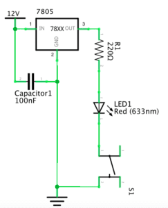
Circuit 1 – Door Bell

Components:

1* Breadboard: to offer a base where the circuit can be built on.

1* Voltage Regulator: regulate the voltage to the proper value of number that can serve the circuit.

1* 12-volt power supply: to get power from the patch board and provide 12V electrical power for the circuit. 

1* Capacitor: to store and release the electrical energy. 

A few hook-up wires: to interconnect the electronic components.

1* Buzzer: to serve as the “door bell”.

 1* Push button (switch): to control the on-off of the door bell.

Diagram:

Picture:

Video:

Process:

Because the door bell was the first circuit I made with my partner, it was also the hardest one. We encountered a lot of problems we have never met before. In the beginning, my partner and I had no idea of how the breadboard functions and how the electricity flows across all those holes. After first asked our assistant Eszter, we figured out how to connect the wires to the power supply and the ground. However, when we connected other electronic components to the breadboard, we made a mistake: we misunderstood the direction of electricity flowing across the breadboard. The direction of electricity should be transverse but we considered it as longitudinal. So we connected the wires to the wrong holes with the components. Thanks to Eszter; she corrected us again. After got all the wires on their right position, we tried to connect the patch board. The door bell rang, however, the switch didn’t work, which means the bell just kept ringing. We checked the circuit again and found that we put the switch in the wrong direction. It was hard to notice that the switch was not near to a cube but to a cuboid, and we must carefully distinguish its inputs and outputs. After corrected this mistake, we finally succeeded! My partner and I were both very excited.

Circuit 2 – Lamp

1* Breadboard: to offer a base where the circuit can be built on.

1* Voltage Regulator: regulate the voltage to the proper value of number that can serve the circuit.

1 * 12-volt power supply: to get power from the patch board and provide 12V electrical power for the circuit. 

1* Capacitor: to store and release the electrical energy. 

A few hook-up wires: to interconnect the electronic components.

1* 220-ohm resistor: to reduce the voltage passing through the LED in order to avoid damage.

1* LED: to give the light after the electricity flows in.

 1* Push button (switch): to control the on-off of the LED.

Diagram:

Picture:

Video:

Process:

The process of making circuit 2 was very smooth. My partner and I found the difference between the diagram of circuit 1 and circuit 2 was only to change the bell into the resistor and LED. So we kept the other electronic components on the breadboard; only removed the bell and connected the resistor and LED in. The process took less than one minute and we succeeded.

Circuit 3 – Dimmable lamp

Components:

1* Breadboard: to offer a base where the circuit can be built on.

1* Voltage Regulator: regulate the voltage to the proper value of number that can serve the circuit.

1 * 12-volt power supply: to get power from the patch board and provide 12V electrical power for the circuit. 

1* Capacitor: to store and release the electrical energy. 

A few hook-up wires: to interconnect the electronic components.

1*  10K ohm Variable Resistor (Potentiometer): to adjust the luminance of LED by adjusting the resistance, changing the voltage passes by the LED.

1* LED: to light up after the electricity flows in.

 1* Push button (switch): to control the on-off of the LED.

Diagram:

Picture:

Video:

Process:

Similar to circuit 2, we found there was only a little difference between circuit 3 and the last one. We switched the resistor in circuit 2 with the variable resistor and soon succeeded. Moreover, after we finished our work, I helped another group to check their circuit 3 and find the reason why it didn’t work. They connected the wire to a wrong hole so that it could not form a pathway for the electricity. After correcting the wire to the right hole, I was happy to see their work succeeded too. 

Additionally, there was actually a non-standard operation made by me when I helped others. I corrected the circuit without powering it out. Such operations could be really dangerous and I’m sure I will pay much more attention to safety next time.

Question 1: After reading The Art of Interactive Design, in what way do you think that the circuits you built today include interactivity? Please explain your answer.

I think the interactivity represents in the responses of the circuits when we press the switch button. As the author states that interactivity is “in terms of a conversation: a cyclic process in which two actors alternately listen, think, and speak”, the circuits can be just considered to include these three elements. When we press the button, the circuit receives a signal; the process is just like the circuit is”listening” to our command. Then the electricity flows into the circuit and searches for a way out; this process is just like “thinking”. In the end, it makes a response, either lights up the LED or rings the bell. The response is similar to “speaking”. Therefore, with all three elements, I think the process that the circuits give responses when we press the button includes the interactivity. 

Question 2: How can Interaction Design and Physical Computing be used to create Interactive Art? You can reference Zack Lieberman’s video or any other artist that you know.

I think Interaction Design and Physical Computing can be used to create Interactive Art by combining the design concept of an interactive artwork and the actual technology of achieving the concept together. In Zack Lieberman’s video, the eye-tracking technology provides a realistic basis for his artistic design, making the product come true. The two things together work out the successful interactive product Lieberman shows in the video. He inspires us that combining the Interaction Design and Physical Computing properly is one way that cannot be ignored during the development of Interactive Art.