Recitation 9: Media Controller Documentation by Eleanor Wade

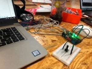
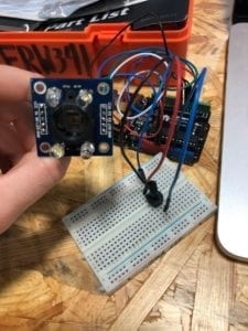
While in class we have used a potentiometer to control media we see on the screen, this recitation I tried to use a different sensor that will eventually be relevant to my final project.  

Working with a Color Sensor!

Because I have never worked with this sensor before and it is totally new to me, I pretty much entirely copied the code from this website and used the explanation of how to use this sensor from this site:

https://randomnerdtutorials.com/arduino-color-sensor-tcs230-tcs3200/

For the most part this link was helpful in both the coding and the putting together of the Arduino components, however I encountered several difficulties not mentioned on this site.  There are definitely challenges in reading different red, green, and blue values. It seems as if the blue colors are always very low, when compared with the others.  I will most likely need to take this into consideration when I am working with this sensor in the future.  Because I plan to use different colored tags, I will definitely need to plan to adjust the blue accordingly.  

Arduino Code: 

// TCS230 or TCS3200 pins wiring to Arduino
#define S0 4
#define S1 5
#define S2 6
#define S3 7
#define sensorOut 8

// Stores frequency read by the photodiodes
int redFrequency = 0;
int greenFrequency = 0;
int blueFrequency = 0;

void setup() {
// Setting the outputs
pinMode(S0, OUTPUT);
pinMode(S1, OUTPUT);
pinMode(S2, OUTPUT);
pinMode(S3, OUTPUT);

// Setting the sensorOut as an input
pinMode(sensorOut, INPUT);

// Setting frequency scaling to 20%
digitalWrite(S0,HIGH);
digitalWrite(S1,LOW);

// Begins serial communication
Serial.begin(9600);
}
void loop() {
// Setting RED (R) filtered photodiodes to be read
digitalWrite(S2,LOW);
digitalWrite(S3,LOW);

// Reading the output frequency
redFrequency = pulseIn(sensorOut, LOW);

// Printing the RED (R) value
//Serial.print(“R = “);
//Serial.print(redFrequency);
delay(100);

// Setting GREEN (G) filtered photodiodes to be read
digitalWrite(S2,HIGH);
digitalWrite(S3,HIGH);

// Reading the output frequency
greenFrequency = pulseIn(sensorOut, LOW);

// Printing the GREEN (G) value
//Serial.print(” G = “);
//Serial.print(greenFrequency);
delay(100);

// Setting BLUE (B) filtered photodiodes to be read
digitalWrite(S2,LOW);
digitalWrite(S3,HIGH);

// Reading the output frequency
blueFrequency = pulseIn(sensorOut, LOW);

// Printing the BLUE (B) value
//Serial.print(” B = “);
//Serial.println(blueFrequency);
delay(100);

Serial.print(redFrequency);
Serial.print(“,”); // put comma between sensor values
Serial.print(greenFrequency);
Serial.print(“,”);
Serial.print(blueFrequency);
Serial.println(); // add linefeed after sending the last sensor value

}

Processing:

In working on the processing code, I have selected photos that will most likely be relevant to my final project from this site:

https://unsplash.com/photos/amI09sbNZdE

And plan to switch between photos when the color sensor picks up on certain colored tags.  
Recitation 10–Tao Wen

This image requires alt text, but the alt text is currently blank. Either add alt text or mark the image as decorative.

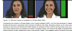
The interaction I built is really simple. Basically, one turns the potentiometer around, and the picture is tinted accrodingly. However, reading the Cheese installation part, I have an idea about how my interaction could be potentially used for. If one smiles, the picture would turn light up accordingly and vice versa. The project could be used to show what people suffering from depression could see in their world, calling people’s attention to and care for this particular group.

Aruduino Part

void setup() {
Serial.begin(9600);
}

void loop() {
int sensorValue = map(analogRead(A0),0,1023,0,255);
Serial.write(sensorValue);
delay(10);
}

Processing Part

size(600, 600);
PImage photo;
photo = loadImage("budapest.jpg");
image(photo, 0, 0);
tint(0, 0, 255, sensorValue);
image(photo, 250, 0);

Project Essay

Project title: collaborative Fourier drawing machine

It is collaborative drawing machine. The project is to stress on, promote and study the human behavior the collaborative work in art design. Many research has been done, including the paper discussing network, Rudi’s video, and a visualization video on Fourier transformation. which, at first gives us a different idea, but after consideration, it lead us finally to this project.

The project consists of a system of nodes that are connected together, each node’s rotation will cause others to rotate as well, the end of the system will has a pen. The users will control the rotation of each node and draw a picture together.
In the following days we will finish three parts:
Arduino: we will make several control machines to the nodes as well as the pen using rotatery encoder, as well as serial communication. We will try two types of the encoder and test their performance. The the device will sent information of the rotation controlled by users to processing, as well as the control flag of the pen, i.e. whether to draw, to erase or nothing.
Processing: we will using oop with sub system idea to design the drawing display. It implies possible advance use of oop including inheritance so that each movement of a node can pass information to its subnodes. it will also involves in complex algorithms to calculate rotation using complex numbers / matrix / inverse trigonometry etc.
Digital fabrication: we will make a cover for the Arduino hardware with each contains a handle for rotation control, a box to but the hardware in and a button shield for drawing control.

As the name suggests, the project is inspired by several research. What makes us want to focus on collaboration are: the paper we found (posted in the proposal) focuses that in a networked system, the individual node is the core essence, and their collaborative work defines the behavior of the whole network. Therefore it gives us the first inspiration. In class Rudi showed us the video that many people ride bicycles to draw display an animation. This inspired us to design a collaborative drawing machine, but the user can design their own drawing. Lastly, the visualization of Fourier transformation inspired us to design the current form. We want to promote the collaboration among people in the design field, and we are also interested in how people will form a collaboration in doing a complex task. Therefore a record will be made by us after observing the collaboration in our project.

Interaction Lab Documentation 9-Kurt Xu

Documentation

In this section, we dig deeper in Arduino’s capability to manipulate the moving pictures, from existing documents, webcam or websites though the Processing.

To the whole project, the key idea is the communication between the Processing and the Arduino. As the transimission is from Arduino to the Processing, we give value in the Arduino and transfer the variarables to the Processing through this function:

1.start the serial library

import processing.serial.*;
Serial myPort;
void setup() {
  myPort = new Serial(this, Serial.list()[ PORT_INDEX ], 9600);

the PORT_INDEX depends on the port that Arduino occupies, which can be identified with this fuction:

printArray(Serial.list());

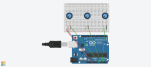
In my function i used three potentiometer to each control the speed, shade and the location of the video (if any key is pressed).

The main problem i face is that the potentiometers are not accurate enough to change the speed of the video, so i divide it for 100 times, and through the map() function, i fix the range of the location and the shade to (0,138) and (0,255) repectively.

Reflection:

In recent years, the art creation with technology involved is becoming more and more popular. Artists are trying to expand the way they can express themselves through their art works, and computers are also trying to expand their recognition of their operators from barely keyboard typing to a more multidimentional aspect, like sound, motion and even video itself, etc. The computer vision is a word that can conclude what i mentioned above, and is widely used “to track people’s activities”(VI,9). I’m deeply interested in that project which stimulates the development of interaction between human and computer, which should be a trend in the coming several decades.

About the project we do in the recitation, it’s actually a semi-computer vision as the computer is translating our manipulation and then manipulate the video accordingly. To improve that, we can expand our way of input, making it less intentional and endow the computer with more autonomy, which means, allowing it to process more on its own.

Work Cited:

Computer Vision for Artists and Designers: Pedagogic Tools and Techniques for Novice Programmers

Video Used:

Recitation 9: Media Controller (November 19, 2019) by Jackson McQueeney

Processing Code:

import processing.serial.*;

Serial myPort;
int valueFromArduino;
import processing.video.*; 
Capture cam;

void setup() {
  size(640, 480); 
  cam = new Capture(this, 640, 480);
  cam.start(); 

  printArray(Serial.list());

  myPort = new Serial(this, Serial.list()[2], 9600);
}


void draw() {
  // to read the value from the Arduino

  while ( myPort.available() > 0) {
    valueFromArduino = myPort.read();
  }
  if (cam.available()) {
    cam.read();
  }
  
  image(cam, 0, 0);
  
  if (valueFromArduino > 200) {
    filter(INVERT);
    println(valueFromArduino);
  }
}

Arduino Code (Input)

const int ledPin = 3;     
const int sensorPin = A0; 

int value; 

void setup(){

  pinMode(ledPin, OUTPUT);  
  Serial.begin(9600);      
  
}

void loop(){

  value = analogRead(sensorPin);                 
  value = map(value, 0, 1023, 0, 255);
  Serial.println(value);      
  analogWrite(ledPin,255-value);          
  delay(100);                          
}

Arduino Code (Communication)

void setup() {
  Serial.begin(9600);
}


void loop() {
  int sensorValue = analogRead(A0) / 4;
  Serial.write(sensorValue);

  
  delay(10);
}

Arduino Circuit:

Result:

Upon activating the force sensor, the colors of the video input invert. 

In Computer Vision for Artists and Designers, the author discusses the application of technology in various fields not traditionally related to technology. Softwares like Processing allow a new focus on the potential visual applications of technology, specifically in the field of visual arts. My code used the computer camera in order to collect visual input, and used Processing’s language to invert the colors from this input. This inversion was activated by a force sensor that the user interacts with.