Final Project Reflection: Snack Facts by Eleanor Wade

Snack Facts – Eleanor Wade – Marcela Godoy

CONCEPTION AND DESIGN:

When considering how my users were going to interact with this project I took much of my research regarding the consumption of animals and animal products, as well as the typical experience of a grocery store in mind.  In order to recreate a similar feeling of the vast array options that consumers are presented with at a super market, I chose to use the color scanner and foods with various colored tags to allow for users to have the experience of checking out at a typical store. Following making their decisions and selecting different products from the shelves (specifically meats with red tags, animal products with blue tags, and plant-based foods with green tags) users would scan to see an overwhelming assortment of pictures and quick facts regarding the process from an industrialized factory farm to table, and the differing environmental impacts each of these actions have.  The color sensor was critical in my design and conception of this experience because it is not only a hands-on and interesting action, but also it can be very clearly linked to the overall feeling of checking out at a grocery store.  It is my hope that many of my users will associate this feeling of blindly making decisions with the pictures that appear on the screen.  While the shelves were made of cardboard, I also included many collected, plastic packages that are commonly used in grocery stores.  This helped to further explore the question of how we process our foods and package them for our convenience, without fully understanding what the consequences of these choices are. Other materials I used, such as real foods (carton of milk, jam, bread, sausages, cookies) were an effort to make the experience appear slightly more realistic.  Additionally, the few edible foods I provided were very beneficial in working to complete the experiences and add an interactive element of taste and smell to the project.  It was evident that these materials–particularly the real, edible foods– were central to the interactive aspect of my project because in addition to using the color sensor, being presented with both plant based and animal based products further made customers question the choices they make everyday.  In associating this specific taste with the exposed realities of the food systems, this project used levels of interactivity to educate people about the environmental impacts of their food choices.  

FABRICATION AND PRODUCTION:

The most significant steps in my production process started with building off of my previous research about animal products and talking with Marcela regarding the best ways to move forward with how to create an interactive and educational experience involving food.  After deciding to use the color sensor, I used my research from a previous recitation using this sensor to work through the Arduino to Processing communication.  In working on the coding of both, and furthering the project by adding a collage of photos from my research, Marcela was exceptionally helpful to me.  I definitely struggled with how to translate the specific numerical values associated with each color and how to connect this to groups of photos.  User testing proved to be very beneficial to me because I was able to engage with users as they were experiencing my project, as well as receive feedback such as the problems with clarity of the text (so later I changed this to only pictures, rather than facts) as well as the speed of the shifting pictures.  Users/”customers” also commented on the action of selecting individual products to scan, as well as the role that edible foods played in the entire understanding of interactivity in my project.  Because of this, I made an effort to select real foods that would be pertinent to the decisions that we make regarding our every meal.  In terms of justifying these aspects of the design, using sample sized foods also supported the various free samples that are commonly found at grocery stores. While the many changes I made to my project following user testing were effective, I think it would have been even better to clarify the images I used, in addition to fixing the distortion, however even after making many different alterations, this was especially difficult.

Digital Fabrication:

3D printing:  https://www.thingiverse.com/thing:2304545

I decided to create a 3D printed mushroom because it represents the produce that is commonly found at a grocery store or supermarket.  I wanted to 3D print rather than laser cut something because I found it relatively easy and beneficial to be able to make shelves out of cardboard, as well as the scanner that contains the Arduino and breadboard for the color scanner.  

CONCLUSIONS:

The primary focus of my project is to educate people on the larger consequences and implications of their food choices.  Through the interactive concept of using a scanner to trigger images specific to food production, I hope to demonstrate the consequences of dietary choices and the larger implications that surround industrialized agriculture and animal farming.  The results of my project align with my definition of interaction because not only do users get to engage with a supermarket-checkout-style scanner, but also they are presented with real, edible foods to further the understanding of what you eat matters. This response from seeing unpleasant or informative images helps to further the elements of interaction in that users both learn something new and associate these facts with the foods they consume regularly.  If I had more time, I would improve my project by fixing the distortion of the images, and by adding sound–specifically the screams of animals living on factory farms as well as a sound that is made after each scan to demonstrate the actions– in order to engage audiences in the experience of the project on a more complete level.  This project has taught me many valuable components, for example the potential that technology and design have for enhancing our understandings of the world and shifting ideologies on even the most basic aspects of life, such as food.  When users are able to experience projects that appeal to more than just one sense, it also enhances the project overall.  Regarding my accomplishments on this project, I am pleased to have been able to use creative technology to be able to introduce people to the realities of food systems that they may have otherwise been very disconnected from.  Ultimately, this project uses visual cues combined with senses such as taste and smell to demonstrate not only compelling methods of interaction, but also help to bridge the gap that we have from how our food is produced.  Audiences and customers should care about this project and experience because it demonstrates the exceptionally detrimental consequences of eating animals and animal products, and translates these very common interactions with food and at grocery stores into more tangible and straightforward pieces of information.  

BIBLIOGRAPHY OF SOURCES:
“5 Ways Eating More Plant-Based Foods Benefits the Environment.” One Green Planet, 21 Aug. 2015, https://www.onegreenplanet.org/environment/how-eating-more-plant-based-foods-benefits-the-environment/.
https://search.credoreference.com/content/entry/abcfoodsafety/avian_flu/0. Accessed 29 Oct. 2018.
“Dairy | Industries | WWF.” World Wildlife Fund, https://www.worldwildlife.org/industries/dairy. Accessed 4 Dec. 2019.
Eating Animals Quotes by Jonathan Safran Foer. https://www.goodreads.com/work/quotes/3149322-eating-animals. Accessed 3 Dec. 2019.
Flu Season: Factory Farming Could Cause A Catastrophic Pandemic | HuffPost. https://www.huffingtonpost.com/kathy-freston/flu-season-factory-farmin_b_410941.html. Accessed 29 Oct. 2018.
“Milk’s Impact on the Environment.” World Wildlife Fund, https://www.worldwildlife.org/magazine/issues/winter-2019/articles/milk-s-impact-on-the-environment?utm_campaign=magazine&utm_medium=email&utm_source=magazine&utm_content=1911-e. Accessed 4 Dec. 2019.
Moskin, Julia, et al. “Your Questions About Food and Climate Change, Answered.” The New York Times, 30 Apr. 2019. NYTimes.com, https://www.nytimes.com/interactive/2019/04/30/dining/climate-change-food-eating-habits.html, https://www.nytimes.com/interactive/2019/04/30/dining/climate-change-food-eating-habits.html.
Nijdam, Durk, et al. “The Price of Protein: Review of Land Use and Carbon Footprints from Life Cycle Assessments of Animal Food Products and Their Substitutes.” Food Policy, vol. 37, no. 6, Dec. 2012, pp. 760–70. DOI.org (Crossref), doi:10.1016/j.foodpol.2012.08.002.
Ocean Destruction – The Commercial Fishing Industry Is Killing Our Oceans. http://bandeathnets.com/. Accessed 3 Dec. 2019.
Siegle, Lucy. “What’s the Environmental Impact of Milk?” The Guardian, 13 Aug. 2009. www.theguardian.com, https://www.theguardian.com/environment/2009/aug/07/milk-environmental-impact.
“The Case for Plant Based.” UCLA Sustainability, https://www.sustain.ucla.edu/our-initiatives/food-systems/the-case-for-plant-based/. Accessed 4 Dec. 2019.
The Ecology of Disease and Health | Wiley-Blackwell Companions to Anthropology: A Companion to Medical Anthropology – Credo Reference. https://search.credoreference.com/content/entry/wileycmean/the_ecology_of_disease_and_health/0. Accessed 29 Oct. 2018.
“WATCH: Undercover Investigations Expose Animal Abusers.” Mercy For Animals, 5 Jan. 2015, https://mercyforanimals.org/investigations.
What Is The Environmental Impact Of The Fishing Industry? – WorldAtlas.Com. https://www.worldatlas.com/articles/what-is-the-environmental-impact-of-the-fishing-industry.html. Accessed 3 Dec. 2019.
Zee, Bibi van der. “What Is the True Cost of Eating Meat?” The Guardian, 7 May 2018. www.theguardian.com, https://www.theguardian.com/news/2018/may/07/true-cost-of-eating-meat-environment-health-animal-welfare.

LED Biking Jacket – Sagar Risal – Rudi

When first creating this jacket I wasn’t really invested in the material of the jacket, since I knew I just needed any jacket that could hold all the circuitry that it would have. I also recognized that the jacket I would need would have to be of a thinner material so that the LEDs could shine through, so I thought it would maybe be a good idea to put a bigger jacket over it, as to hide the wiring. In the end I ended up not having the bigger jacket over it, since I thought I did a good job of hiding the sewing  I did on the jacket. I also knew the user would need a way to turn on the indicators in a way that would be easy for the user to do as well as safe for when they would be biking. For this reason I decided to add gloves to the jacket so that the user had access to buttons.  I then decided that I would put the buttons on the gloves near the finger so that the user had very easy access to pressing the button and indicating in which direction they were going. I thought of maybe purchasing a real biking jacket with actual biking gloves, as to make the outfit feel more legitimate, but the overall cost steered me to instead find a cheap jacket. If I had a lot more time, and money, I would’ve loved to integrate the wires inside the actual jacket material, so they wouldn’t show.

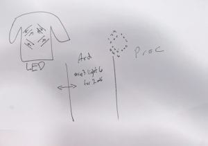
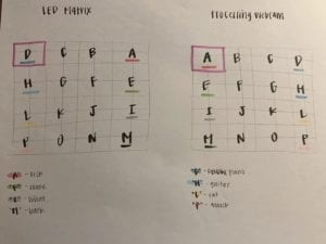
While creating the jacket there were three main humps. These were, the actual design of jacket and how I would make it and how it would look, the communication between Arduino and Processing and how it would play into the jacket, as well as how the lights would look. These three were all huge parts of the production of the jacket and how it would turn out in the end. One of the biggest struggles for me at first was how I would be able top have LEDs on the back of the jacket showing animations. At first I thought having an LED matrix on the back of the jacket would be a good idea, but after looking at the schematics of it and how much time it would take to do it, I thought that it would be better to have four LED strips and control each individual LED strip to make the desired animations. This would make it a lot easier to make the jacket itself, as well as code for the animations. This decision was a big part of how I would proceed to do my project, since the matrix idea was more Processing based, while having four LED strips would be handled majority by Arduino. I would say that I ended up coming successful in these three humps, except for the fact that I didn’t have time to code for the ability for the user to change the colors of the jacket, which I thought would be a really nice addition. 

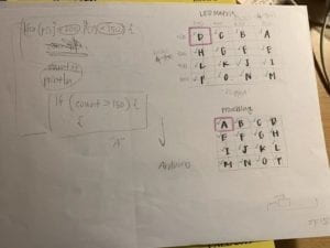
Matrix Sketch                                      Four LED Strips Sketch

IMG_4887

In user testing I was missing majority of my project, and though most students liked the idea of LEDs on a jacket and being able to control them for the practical purpose of riding a bike, many of the teachers wanted me to add more elements to the jacket, which is where one of my proudest success came from. Ironically the success wasn’t from the jacket but instead the interface of which one could interact on Processing with the jacket.  I was really proud of the interface because of how it complemented the theme of the jacket, as well as do nice job of showing the interaction between the user and the jacket through the computer. The interface allowed me to play more with the theme that the jacket would follow, as well as how the user would be able to interact with the jacket, while still following the practical use of the jacket itself.  

When I set out to make this project I wanted to make a jacket that could be worn by bikers, so that when they bike at night they are able to be seen by cars as well as by other bikers who, especially at night, don’t know in which direction one is turning. After witnessing many biking accidents here in China, as well as being in a couple myself, I noticed that most of them happen at night    where visibility is low and riding itself is difficult because of the fact bikes have to share the road with pedestrians as well as electric scooters. I wanted an easy as well as cool way in which bikers could safely traverse the streets without feeling like they can’t be seen. I also wanted the driver to interact with the jacket itself, which is why I added buttons, as well as an interface where the user can change the animations to what they want. I have always defined interaction in levels instead of just having interaction, or not having. Obviously just pressing buttons on a jacket isn’t much of an interaction, but when thinking about the bigger picture of how one is able to choose what animations they want on their jacket as well how the usage of the jacket itself and how it lends to interacting with people on the streets while biking, it shows how just be able to control what your clothes do on your body you are able to interact with more than just two buttons on your gloves. 

During my final presentation many of my peers enjoyed the project, but also offered many recommendations that I myself wanted to include in the project but I couldn’t because of time. This included a brake light, as well as feedback for the user when pressing the buttons, so that the user could have some indication that the lights were working in the right way, since the user cannot see the lights themselves. These were all recommendations that I thought were very helpful towards how I could improve the jacket. If I had more time with this project I would’ve loved to add more customization options, as well as take the recommendations I received into my project. I would have also loved to improve on the look of the jacket itself, so that it can look and feel like a regular bike jacket but have LEDs as well. 

One thing that I definitely learned from this project is that combining technology with fashion, or just clothes in general, takes a lot of time, effort and patience. Not everything works the first time and one has many different factors when designing a meaningful way to use technology in ones clothes. The whole process is very tiresome but very rewarding when one is able to do it successfully, making the technology work meaningfully as well as look good.   Clothing and technology, while two very different things, are a lot more similar than one thinks. While humans start using technology more and more in their daily lives, it should be natural that we start adapting it to fit our clothes, which is also necessary for every day use. The more and more comfortable we get with technology and how we can implement it into what we wear, the easier daily life can become, with having simple tasks be able to be done from our clothes instead of our phone or additional technology. My LED biking jacket shows something as simple as a jacket with lights can be used to help solve issues of safety on the road, as well as offer a different style to the bikers who use it. As technology gets better and more incorporated into what we wear, one will be able to interact easier with more from their daily lives, from the simple action of just wearing their clothes. These interactions we have with what we wear, not only can look really cool, but also have a big impact with how we interact with each other in the future.

Arduino Code: 

#include <FastLED.h>
#define LED_PIN 7
#define LED_PIN_2 6
#define LED_PIN_3 5
#define LED_PIN_4 4
#define NUM_LEDS 18

#define NUM_OF_VALUES 3 /** YOU MUST CHANGE THIS ACCORDING TO YOUR PROJECT **/
/* This is the array of values storing the data from Processing. */
int values[NUM_OF_VALUES];
int valueIndex = 0;
int tempValue = 0;

CRGB leds[NUM_LEDS];
CRGB leds_2[NUM_LEDS];
CRGB leds_3[NUM_LEDS];
CRGB leds_4[NUM_LEDS];

int leftButton = 8;
int rightButton = 9;

void setup() {
Serial.begin(9600);
values[0] = 1;
values[1] = 1;
values[2] = 1;
FastLED.addLeds<WS2812, LED_PIN, GRB>(leds, NUM_LEDS);
FastLED.addLeds<WS2812, LED_PIN_2, GRB>(leds_2, NUM_LEDS);
FastLED.addLeds<WS2812, LED_PIN_3, GRB>(leds_3, NUM_LEDS);
FastLED.addLeds<WS2812, LED_PIN_4, GRB>(leds_4, NUM_LEDS);

//LEFT SIGNAL
pinMode(leftButton, INPUT_PULLUP);

//RIGHT SIGNAL
pinMode(rightButton, INPUT_PULLUP);

}

void loop() {

getSerialData();

if (digitalRead(leftButton) == LOW) {
//Play left animation
if (values[0] == 1) {
Left1();
Left1();
Left1();

}
if (values[0] == 2) {
Left2();
Left2();
Left2();

}
if (values[0] == 3) {
Left3();
Left3();
Left3();

}
}
else if (digitalRead(rightButton) == LOW) {
//Play right animation
if (values[2] == 1) {
Right1();
Right1();
Right1();

}
if (values[2] == 2) {
Right2();
Right2();
Right2();

}
if (values[2] == 3) {
Right3();
Right3();
Right3();

}
}
else {
if (values[1] == 1) {
Forward1();
}
if (values[1] == 2) {
Forward2();
}
if (values[1] == 3) {
Forward3();
}
}

}

void Direction1() {

for (int i = 18; i >= 0; i–) {
leds[i] = CRGB (255, 0, 0);
FastLED.show();
delay(40);
}

for (int i = 18; i >= 0; i–) {
leds[i] = CRGB (0, 0, 0);
FastLED.show();
delay(40);
}

}

void Direction2() {

for (int i = 0; i <= 18; i++) {
leds[i] = CRGB ( 255, 0, 0);
FastLED.show();
delay(40);
}
for (int i = 0; i <= 18; i++) {
leds[i] = CRGB ( 0, 0, 0);
FastLED.show();
delay(40);
}

}

void Blink() {

leds[0] = CRGB(255, 0, 0);
leds[1] = CRGB(255, 0, 0);
leds[2] = CRGB(255, 0, 0);
leds[3] = CRGB(255, 0, 0);
leds[4] = CRGB(255, 0, 0);
leds[5] = CRGB(255, 0, 0);
leds[6] = CRGB(255, 0, 0);
leds[7] = CRGB(255, 0, 0);
leds[8] = CRGB(255, 0, 0);
leds[9] = CRGB(255, 0, 0);
leds[10] = CRGB(255, 0, 0);
leds[11] = CRGB(255, 0, 0);
leds[12] = CRGB(255, 0, 0);
leds[13] = CRGB(255, 0, 0);
leds[14] = CRGB(255, 0, 0);
leds[15] = CRGB(255, 0, 0);
leds[16] = CRGB(255, 0, 0);
leds[17] = CRGB(255, 0, 0);

FastLED.show();
delay(500);
leds[0] = CRGB(0, 0, 0);
leds[1] = CRGB(0, 0, 0);
leds[2] = CRGB(0, 0, 0);
leds[3] = CRGB(0, 0, 0);
leds[4] = CRGB(0, 0, 0);
leds[5] = CRGB(0, 0, 0);
leds[6] = CRGB(0, 0, 0);
leds[7] = CRGB(0, 0, 0);
leds[8] = CRGB(0, 0, 0);
leds[9] = CRGB(0, 0, 0);
leds[10] = CRGB(0, 0, 0);
leds[11] = CRGB(0, 0, 0);
leds[12] = CRGB(0, 0, 0);
FastLED.show();
delay(500);
}

void getSerialData() {
while (Serial.available() > 0) {
char c = Serial.read();
//switch – case checks the value of the variable in the switch function
//in this case, the char c, then runs one of the cases that fit the value of the variable
//for more information, visit the reference page: https://www.arduino.cc/en/Reference/SwitchCase
switch (c) {
//if the char c from Processing is a number between 0 and 9
case ‘0’…’9′:
//save the value of char c to tempValue
//but simultaneously rearrange the existing values saved in tempValue
//for the digits received through char c to remain coherent
//if this does not make sense and would like to know more, send an email to me!
tempValue = tempValue * 10 + c – ‘0’;
break;
//if the char c from Processing is a comma
//indicating that the following values of char c is for the next element in the values array
case ‘,’:
values[valueIndex] = tempValue;
//reset tempValue value
tempValue = 0;
//increment valuesIndex by 1
valueIndex++;
break;
//if the char c from Processing is character ‘n’
//which signals that it is the end of data
case ‘n’:
//save the tempValue
//this will b the last element in the values array
values[valueIndex] = tempValue;
//reset tempValue and valueIndex values
//to clear out the values array for the next round of readings from Processing
tempValue = 0;
valueIndex = 0;
Flash();
Flash();
Flash();
break;
//if the char c from Processing is character ‘e’
//it is signalling for the Arduino to send Processing the elements saved in the values array
//this case is triggered and processed by the echoSerialData function in the Processing sketch
case ‘e’: // to echo
for (int i = 0; i < NUM_OF_VALUES; i++) {
Serial.print(values[i]);
if (i < NUM_OF_VALUES – 1) {
Serial.print(‘,’);
}
else {
Serial.println();
}
}
break;
}
}
}

Processing Code: 

import processing.serial.*;

int NUM_OF_VALUES = 3; /** YOU MUST CHANGE THIS ACCORDING TO YOUR PROJECT **/

Serial myPort;
String myString;

// This is the array of values you might want to send to Arduino.
int values[] = {1,1,1};
char screen = ‘H’;

void setup() {

size(1440, 900);

printArray(Serial.list());
myPort = new Serial(this, Serial.list()[ 5 ], 9600);
// check the list of the ports,
// find the port “/dev/cu.usbmodem—-” or “/dev/tty.usbmodem—-”
// and replace PORT_INDEX above with the index of the port

myPort.clear();
// Throw out the first reading,
// in case we started reading in the middle of a string from the sender.
myString = myPort.readStringUntil( 10 ); // 10 = ‘\n’ Linefeed in ASCII
myString = null;
imgLeft = loadImage(“LeftReal.jpg”);
imgMenu = loadImage(“Menu.jpg”);
imgForward = loadImage(“Forward.jpg”);
imgRight = loadImage(“Right.jpg”);
}

void mousePressed() {
if (screen == ‘H’) {
mousePressHome();
} else if (screen==’L’) {
mousePressLeft();
} else if (screen==’F’) {
mousePressForward();
} else if (screen==’R’) {
mousePressRight();
}

//sendSerialData();
}

void sendSerialData() {
String data = “”;
for (int i=0; i<values.length; i++) {
data += values[i];
//if i is less than the index number of the last element in the values array
if (i < values.length-1) {
data += “,”; // add splitter character “,” between each values element
}
//if it is the last element in the values array
else {
data += “n”; // add the end of data character “n”
}
}
//write to Arduino
myPort.write(data);
}

void echoSerialData(int frequency) {
//write character ‘e’ at the given frequency
//to request Arduino to send back the values array
if (frameCount % frequency == 0) myPort.write(‘e’);

String incomingBytes = “”;
while (myPort.available() > 0) {
//add on all the characters received from the Arduino to the incomingBytes string
incomingBytes += char(myPort.read());
}
//print what Arduino sent back to Processing
print( incomingBytes );
}

void draw()//Title Screen
{
if (screen == ‘H’) {
drawHome();
} else if (screen == ‘L’) {
drawLeft();
} else if (screen == ‘F’) {
drawForward();
} else if (screen == ‘R’) {
drawRight();

}

// echoSerialData(20);
}

void keyPressed() {
printArray(values);
sendSerialData();
}

Creative Motion – Yu Yan (Sonny) – Inmi

Creative Motion – Yu Yan (Sonny) – Inmi

Conception and Design:

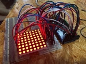
During the brainstorming phase, my partner Lillie and I tended to build an interactive project that allows users to create digital paintings only with their motions. The interaction of this project includes users’ movements as the input and the image displayed on the digital device as the output. Our enlightenment comes from Leap Motion interactive art exhibit. At this point, we thought about using multiple sensors on Arduino to catch the movements, and display the image on Processing. However, after we tried on several sensors and did some researches, we found that there is no sensor suitable for our needs and even if there is, it would take a huge amount of time to build the circuit and understand how to code. So we turned to our instructor for help and also did some further researches to see other alternative ways. Finally, we decided to use the webcam in Processing as our “sensor” to catch the input (users’ movements) and build an LED board on Arduino to display the output (painting). The reasons why we choose the webcam are that it’s easier to catch images from the camera than from the sensor, the color values detected from the camera are more accurate than from the sensor, and the code is not too difficult to learn with the help of other IMA fellows. However, when we were figuring out the Arduino part, we found it hard to build the circuit using single-colored LEDs and connect all of them on the breadboard. With our further researches, we managed to find that the 8*8 LED matrix can replace the single-colored LEDs and also generate more colors. But the first few pieces of LED matrix are not satisfactory because we don’t know how to connect them to the Arduino board and we were unable to find the solutions online (We found this video that we thought it would be helpful for us to understand how to connect the LED matrix to the Arduino, but it wasn’t). We also found a sample code to test the LED matrix, but since we were unable to connect it to the Arduino, this code became useless as well. Moreover, those pieces can only generate three colors that didn’t meet our needs.

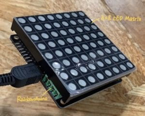
Since we want to allow users to create paintings with more diversity, we tried to find the LED matrix that can display in rainbow colors. After consulting with other IMA fellows, we found that the Rainbowduino can work with one kind of LED matrix and display in rainbow colors. The code for this is also easy to comprehend. So eventually, we decided to use the Rainbowduino and the LED matrix in Arduino as our output device, and the webcam in Processing as our input detector. 

Fabrication and Production:

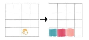
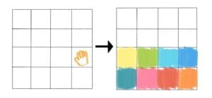
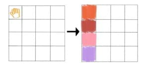
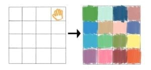
One of the most significant steps in our production process in terms of failures are the coding phase. Since when we chose materials for the output device, we tried quite a few kinds of LED matrix and also looked for their codes, we discovered that the code for previous LED matrix are too complex to comprehend. We needed to set different variables for different rows and columns of the LEDs, which is quite confusing sometimes. But after we decided to use the Rainbowduino, the code for Arduino became much easier because we can use the coordinate to code for each single LED. And with the help of IMA fellows, we managed to write the code that satisfied our needs. This experience tells us that choosing suitable equipment is very crucial to a project,  for choosing a good one can bring great convenience to the progress and save us a lot of time. Another significant step is the feedback we received during the user testing session. The good things are that many users showed their interests to our project and thought it’s really cool when displaying different colors. They all thought the interaction with the piece is quite intriguing and they liked that their movements can light up the LEDs in different colors. This feedback meets our initial goal of providing users with opportunities to create their own art using their motions. However, there were still some problems we can still improve. First of all, one of the users said that the way the LEDs lighted up could be a little confusing because it cannot well illustrate where the user moves. It’s because we didn’t separate the x-axis and the y-axis for each section of LEDs at first. The following sketches and video help explain the situation.

To solve this issue, we modified our code and separated the x-axis and the y-axis for each section so that it can light up without causing other sections of LEDs lighting up as well. After we showed our modified project to the user who gave us this comment, he said that the experience is better now and he can see himself moving in the LED matrix more clearly. Second, the experience of interaction could be too single and boring and it’s hard to convey our message to users through this experience. Since the interaction is only about moving their bodies and displaying different colors in the same position of their movements on the LED matrix, it might be too stuffless for an interactive project. Marcela and Inmi suggested that maybe adding some sounds to it can make it more attractive and more meaningful. So we took their advice. In addition to turning up a section of LEDs when moving to the relative area, we also added some sound files to each section of LEDs and made them play with the lighting up of the corresponding LEDs. The following sketches illustrate how we defined each section and different sound file.


Initially, we used several random sounds such as “kick” and “snare” because we wanted to bring more diversity into our project. But during the presentation, some users commented that the sound is too random and sounded chaotic when they were all turned on. One of them also mentioned that the sound of “snapshot” made her feel uncomfortable. So for the final IMA show, we adjusted all the sound files to different key notes of the piano. This change made the sound more harmonious and comfortable to hear when users are interacting with the project. Third, some users mentioned that the LED matrix is too small and sometimes they might neglect the LED and pay more attention to the computer screen instead. At first, we thought about connecting more LED matrixes together and making a bigger screen, but we didn’t manage to do that. So instead of magnifying the LED matrix, we made the computer screen more invisible and the LED matrix more outstanding by putting it into our fabrication box. The result turned out to be much better than before and we caught users’ attention to our LED matrix instead of the computer screen.

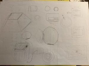
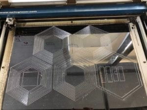
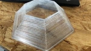
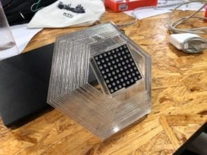
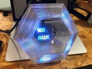
By contrast, the fabrication process is one of the most significant steps of our project in terms of success. Before we settled down the final polygon shape, we came up with a few other shapes as well. Similar to my midterm project, we also chose Laser-cut and glued each layer together to build the shape. Since we wanted to make something cool and make the most use of our material, we decided to choose transparent plastic board to make the shape. We also discovered that polygon can help build a sense of geometric beauty, so finally, we made our box into a polygon shape. At first, we tended to just put the LED matrix on the top of the polygon. But one of IMA fellows suggested that we can put the LED matrix at the bottom of the polygon so that the light can reflect through the plastic and make it prettier. Thanks to this advice, it turned out to be a really cool project!


Conclusions:

For our final project, our goal is always allowing people to create their own art using their motions and also encourage them to create art in different forms. Although we changed our single output (painting) to multiple outputs (painting and music), our goal of creating art with motions still remains the same. Initially, we defined interaction as a continuous communication between two or more corresponding elements, an iterative process which involves actions and feedbacks. Our project successfully aligned with our definition by creating a constant communication between the project and the users and providing immediate feedback to users’ motions. However, the experience of interacting with the piece is still not satisfactory enough because we could not magnify the LED matrix so that it’s too small to notice. We didn’t create the best experience to users. But fortunately, most of the users understood that they can change the image and create different sounds with their motions. They all thought that this is a really interesting and interactive project that they can play with for a long time. Some users even tried to play a full song after they discovered the location of each keynote. If we had more time, we would definitely build a bigger LED board to make it easier for users to experience the process of creating art with their motions. The setbacks and obstacles we’ve encountered are all seemed quite fair during the process of completing a project. But the most important thing is to learn some lessons from these setbacks and obstacles. What I learned from them are that we should humbly take people’s comments about our project and turn them into useful improvements and motivations. In addition, I noticed that I still didn’t pay enough attention to the experience of the project. Since experience is one of the most vital parts of an interactive project, it should always be the first consideration. However, I also learned that the reason why many people like our project is that it can display their existence and be controlled by them. Users are in charge of everything the project displays. This also shows that we have created a tight and effective communication between the project and users. Furthermore, making the most use of our materials is also very important. Sometimes it can make a big change to the whole project and turn it into a more complete version. Since nowadays many people still hold the concept that art can only be created in those limited forms, we want to break this concept by providing them with tools to create new forms of art and inspiring them to think outside of the box. Art is limitless and with great potential. By showing that motion can also create different forms of art, this project is not only a recreation but also an enlightenment to help people generate more creative ideas of new forms of art and free their imagination. It also helps make people be aware of their ability and their “power”, and let them control the creation of art. “Be bold, be creative, and be limitless.” This is the message we want to convey to our audience. 

The code for Arduino is here. And the code for Processing is here.

Now, let’s have a look at how our users interact with our project!

Recitation 10 Documentation – Jackson Simon

For this recitation, the workshop recitation, I decided to attend the one on Serial Communication by Mister Young. I feel it was quite important for my project, since I would need to both be communicating from Arduino to Processing and Processing to Arduino at the same time.

I learned how to make a sensor value from the Arduino influence Processing (for example, in my Final Project, an accelerometer influenced whether the game would continue in Processing).

In this simple example shown in the video below, I connect an Infrared Sensor to Arduino and map the values from 0-1023 to 0-50 and have them being read in Processing.

It ended up being useful (at the start of my project, before I decided to have the start of the game be a different way than with an infrared sensor) since when a person would walk in front of the sensor it would turn on the game in Processing, and start the audio from Processing.

Familiar Faces-Christina Bowllan-Inmi Lee

Familiar Faces- Christina Bowllan- Inmi Lee

For our final project, Isabel and I wanted to address why it is that people do not naturally befriend others from different cultures. While this of course does not relate to everyone, we realized in our school that people who speak the same language oftentimes hang out together and people from the same country do as well. This does answer one part of the question, but the real problem is we fail to realize that people from other cultures are more similar to us than we think; We all have hobbies, hometowns, things we love to do, foods that we miss from our hometowns, struggles within our lives, etc. In order to illustrate this, we interviewed several workers within our school such as the aiyis and halal food people because we wanted to open their stories since they are a group in our school that we often overlook. 

827 (Video 1)

829(Video 2)

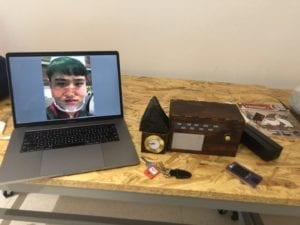
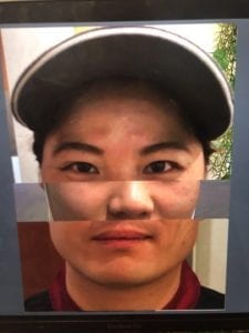
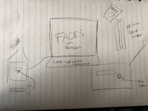
In order to create this project, we had three different sensor spots: one was a house, one was a radio and one was a key card swiper. When the user would push the key inside the house, the audio relating to the workers’ home experience would play, the radio played miscellaneous sound clips about what they missed from their hometown or what they do in Shanghai over the weekends, and the card swiper randomized their faces on the processing image. We decided to create these different physical structures because we wanted each to be a representation of a different aspect of their lives and we created the processing image in order to show people our stories are not that different than one another— after all, we all have eyes, a nose and a mouth. We tried to make the interaction resemble what people do in their everyday lives, or if they do not use a radio, for example, have different structures that the users would already know how to interact with. On the whole, this worked because people knew how to use the card for the swiper and push the radio button, but for some reason, people did not understand what they should do with the key. So, in order to construct each part, we did a lot of laser cutting as this is what our house and radio were made out of it. This proved to be a great method because the boxes were really easy to put together, they looked clean, and the radio could hold our arduino as well. In the early stages, we had thought about maybe 3d printing, but it would be hard to construct a sensor inside this material. For the card swiper, it would have been too difficult to build all of the pieces for laser cutting, so we designed it using cardboard, which proved to be effective. We were able to tape up the various sides and it held the sensor in place very well, so the interaction between processing and arduino was, spot on!

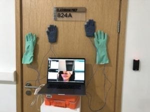
Above shows how our final project ended up, but it did not start this way. Our initial idea was to hang four different types of gloves on the wall which would all represent people from different backgrounds and classes. And the user was intended to high five the gloves which would change the randomized face simulation to show if we cooperate and get to know one another, we can understand that our two worlds are not that different. For user testing, we had the gloves and the randomized face simulation, but the interaction was a bit basic. At first we wanted to put LED lights on each glove so that people could have more of a reason to interact with our game, but the project in general was not conveying our meaning. Users found the project cool and liked seeing pictures of their friends change on the screen, but they did not recognize the high five element to show cooperation or the bigger idea. The main feedback we got was that we needed to be more specific in what it means for people from all backgrounds to come together.

At this point, we decided to create what was our final project and focus in on a certain group of people to show that we have shared identities. So, while the gloves were great, we did not end up using them, and we created the house, radio and card swiper to show different connection points between people. 

For our project, we wanted to show people that we are not so different after all and we used the different workers within our school to illustrate this idea. Our project definitely aligned with my definition; We did have “a cyclic process in which two actors, think and speak” (Crawford 3) and we created a meaningful interaction which we should strive for in this class. Ultimately, I think people did understand our project through the final version we created, but if we continued working on it, of course we could make some changes. Some examples included, we could add subtitles of the interviews so that English speakers understand and Tristan had a good idea to add a spotlight so people know which interaction to focus on. Also, I mentioned this above, but people did not really know what to do with the key… It ended up working out because I believe that slowly understanding what to do with each part resembles what it’s like to get to know someone, but this was not our intended interaction. I have learned from doing this project that “all. good. things. take. time”. I am so used to “cranking out” work in school and then not looking at it again, so it became tedious having to fix different dilemmas here and there. But, once I did the interviews and constructed the card swiper by myself, I felt a wave of confidence and that motivated me to keep working on the project. Overall, people should care about our project because if you care about building a cohesive and unified community and improving school spirit, this is an unavoidable first step. 

CODE

Arduino Code:

// IMA NYU Shanghai
// Interaction Lab
// For sending multiple values from Arduino to Processing

void setup() {
Serial.begin(9600);
}

void loop() {
int sensor1 = digitalRead(9);
int sensor2 = digitalRead(7);
int sensor3 = digitalRead(8);

// keep this format
Serial.print(sensor1);
Serial.print(“,”); // put comma between sensor values
Serial.print(sensor2);
Serial.print(“,”);
Serial.print(sensor3);
Serial.println(); // add linefeed after sending the last sensor value

// too fast communication might cause some latency in Processing
// this delay resolves the issue.
delay(100);
}

Processing Code:

// IMA NYU Shanghai
// Interaction Lab
// For receiving multiple values from Arduino to Processing

/*
 * Based on the readStringUntil() example by Tom Igoe
 * https://processing.org/reference/libraries/serial/Serial_readStringUntil_.html
 */

import processing.serial.*;
import processing.video.*; 
import processing.sound.*;
SoundFile sound;
SoundFile sound2;

String myString = null;
Serial myPort;


int NUM_OF_VALUES = 3;   /** YOU MUST CHANGE THIS ACCORDING TO YOUR PROJECT **/
int[] sensorValues;      /** this array stores values from Arduino **/
int[] prevSensorValues;


int maxImages = 7; // Total # of images
int imageIndex = 0; // Initial image to be displayed
int maxSound= 8;
int maxSound2= 10;
boolean playSound = true;
// Declaring three arrays of images.
PImage[] a = new PImage[maxImages]; 
PImage[] b = new PImage[maxImages]; 
PImage[] c = new PImage[maxImages]; 
//int [] d = new int [maxSound];
//int [] e = new int [maxSound2];
ArrayList<SoundFile> d = new ArrayList<SoundFile>();
ArrayList<SoundFile> e = new ArrayList<SoundFile>();

void setup() {

  setupSerial();
  size(768, 1024);
  prevSensorValues= new int [4];

  imageIndex = constrain (imageIndex, 0, 0);
  imageIndex = constrain (imageIndex, 0, height/3*1);
  imageIndex = constrain (imageIndex, 0, height/3*2);  
  // Puts  images into eacu array
  // add all images to data folder
  for (int i = 0; i < maxSound; i++ ) {
    d.add(new SoundFile(this, "family" + i + ".wav"));
  }
  for (int i = 0; i < maxSound2; i ++ ) {

    e.add(new SoundFile(this, "fun" + i + ".wav"));
  }
  for (int i = 0; i < a.length; i ++ ) {
    a[i] = loadImage( "eye" + i + ".jpg" );
  }
  for (int i = 0; i < b.length; i ++ ) {
    b[i] = loadImage( "noses" + i + ".jpg" );
  }
  for (int i = 0; i < c.length; i ++ ) {
    c[i] = loadImage( "mouths" + i + ".jpg" );
  }
}


void draw() {
  updateSerial();
  // printArray(sensorValues);
  image(a[imageIndex], 0, 0);
  image(b[imageIndex], 0, height/2*1);
  image(c[imageIndex], 0, height/1024*656);


  // use the values like this!
  // sensorValues[0] 
  // add your code
  if (sensorValues[2]!=prevSensorValues[2]) {
    //imageIndex += 1;
    println("yes");
    imageIndex = int(random(a.length));
    imageIndex = int(random(b.length));
    imageIndex = int(random(c.length));//card
  }
  if (sensorValues[1]!=prevSensorValues[1]) {
    //imageIndex += 1;
    println("yes");
    
    int soundIndex = int(random(d.size()));//pick a random number from array
    sound = d.get(soundIndex); //just like d[soundIndex]
    
    if (playSound == true) {
      // play the sound

      sound.play();
      // and prevent it from playing again by setting the boolean to false
      playSound = false;
    } else {
      // if the mouse is outside the circle, make the sound playable again
      // by setting the boolean to true
      playSound = true;
    }
  }
  if (sensorValues[0]!=prevSensorValues[0]) {
    //imageIndex += 1;
    println("yes");
  
    int soundIndex = int(random(e.size()));
    sound2 = e.get(soundIndex); //just like e[soundIndex]
    if (playSound == true) {
      // play the sound
      sound2.play();
      // and prevent it from playing again by setting the boolean to false
      playSound = false;
    } else {
      
      playSound = true;
    }
  }

  prevSensorValues[0] = sensorValues[0];
  println(sensorValues[0], prevSensorValues[0]);
  println (",");
  prevSensorValues[1] = sensorValues[1];
  println(sensorValues[1], prevSensorValues[1]);
  println (",");
  prevSensorValues[2] = sensorValues[2];
  println(sensorValues[2], prevSensorValues[2]);

}


void setupSerial() {
  printArray(Serial.list());
  myPort = new Serial(this, Serial.list()[ 1 ], 9600);
  // WARNING!
  // You will definitely get an error here.
  // Change the PORT_INDEX to 0 and try running it again.
  // And then, check the list of the ports,
  // find the port "/dev/cu.usbmodem----" or "/dev/tty.usbmodem----" 
  // and replace PORT_INDEX above with the index number of the port.

  myPort.clear();
  // Throw out the first reading,
  // in case we started reading in the middle of a string from the sender.
  myString = myPort.readStringUntil( 10 );  // 10 = '\n'  Linefeed in ASCII
  myString = null;

  sensorValues = new int[NUM_OF_VALUES];
}


void updateSerial() {
  while (myPort.available() > 0) {
    myString = myPort.readStringUntil( 10 ); // 10 = '\n'  Linefeed in ASCII
    if (myString != null) {
      String[] serialInArray = split(trim(myString), ",");
      if (serialInArray.length == NUM_OF_VALUES) {
        for (int i=0; i<serialInArray.length; i++) {
          sensorValues[i] = int(serialInArray[i]);
        }
      }
    }
  }
}