First Lab Post

Lab Date: Feb 15, 2019

Instructor: Marcela

Lab Partner: Julie Huang

Circuit One:

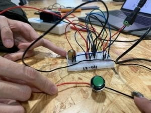
Displaying IMG_1873.jpg

Circuit One Components:

1x Buzzer: Creates beeping sound when there is an electric current flow.

1x 100 nF Capacitor: Acts as a power supply

1x Push Button Switch: Starts or stop connection in the electric circuit

1x LM7805 Voltage Regulator: To regulate and maintain a voltage level. In this circuit it helped transfer 12V voltage level to 5V voltage level

1x Breadboard: A construction base for connecting components

1x 12 Voltage Power Supply: Acts as a stable power source

1x Barrel Jack: Used to connect extra low voltage devices to external electricity.

Jumper Cables: To connect components and pieces.

Where is the power?

While connecting the jumper cables to the breadboard, Instructor Nick spotted a mistake about our circuit. He pointed out the jumper cables that are connected to provide power for the rows and we must connect other jumper cables to those specific rows to create a circuit.

Circuit Two:

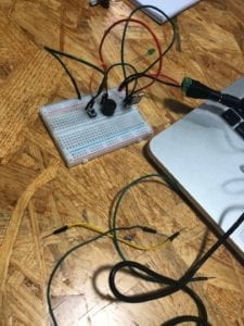
Displaying IMG_1876.jpg

Circuit Two Components:

1x Breadboard: A construction base for connecting components.

1x LM7805 Voltage Regulator: To regulate and maintain a voltage level. In this circuit, it helped transfer 12V voltage level to 5V voltage level.

1x Push Button Switch: Starts or stop connection in the electric circuit.

1x Arcade Button: A button that had to be soldered but is able to connect the whole circuit when pressed.

1x 220-ohm Resistor: To reduce current flow

1x LED: Omits light when connected to a power source

1x Barrel Jack: Used to connect extra-low voltage devices to external electricity.

Jumper Cables: To connect components and pieces.

1x nF (0.1uF) Capacitor: To store electrical energy

1x 12V power supply: Provides power source

1x Multimeter: Measures voltage, resistance, and current.

How do you efficiently use the breadboard?

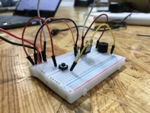
While trying to put circuit two together, we realize the buzzer occupied quite a lot of breadboard space. Therefore my partner and I, with the help of the professors, decided to plant the buzzer on two different sections of the motherboard (as indicated on the picture above). 

Circuit Three:
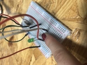
Circuit Three Components:

1x Breadboard: A construction base for connecting components.

1x LM7805 Voltage Regulator: To regulate and maintain a voltage level. In this circuit, it helped transfer 12V voltage level to 5V voltage level.

1x Push Button Switch: A switch that is able to connect the whole circuit when pressed.

1x 220-ohm Resistor: To reduce current flow

1x 10k oHm Variable Resistor (Potentiometer): To change resistance in a closed circuit.

1x LED: Omits light when connected to a power source.

1x 100 nF (0.1uF) Capacitor: Stores electrical energy.

1x 12 Volt power supply: Provides power source

1x Barrel JackUsed to connect extra-low voltage devices to external electricity.

Jumper Cables: To connect components and pieces.

1x Multimeter: Measures voltage, resistance, and current.

How can we organize our breadboard?

While trying to attempt circuit three, my partner and I quickly realize it was the most complex out of all the challenges. Circuit three required the most jumper cables and cables are confusing and easy to tangle up. Therefore we decided to use different colored cables and spread out the cables in order to make the circuit three easier.

Reflection:

I did not encounter a huge problem trying to put the pieces together for the different circuits. Instead, my partner and I had a more difficult time trying to envision how we can place the components together to achieve the goal. As it is our first time trying to understand how electricity works, we had to consult the professors regarding how we can work out the diagrams. However after we had a general idea/pattern, we learned the ideas and employed it onto the circuits following circuit one.

Answers:

Question One:

After reading the text, I realize the circuits we built today included interactivity as all circuits included an input, an output, and a process. Although these circuits can be considered a lower degree of interaction, it still took two parties to create a reaction. One party is the circuit and the other party being the conductors (my partner and I) pressing a switch. Therefore, I believe our circuits do include interactivity, according to the definition found in the article.

Question Two:

After building the three circuits, I believe we were introduced to the interactive design component but I feel like physical computing is vital to being able to create Interactive Art.  Physical computing and interaction design both involve building interactive software that consists of a stimulus and a response. By creating interactive software that can provide a different response, it attracts users to attempt different stimulus. Especially with technology advancements, the potential templates for interactive art is plentiful and the future is broad.
Interaction Lab: Exercise 1 Documentation — Kenan Gu

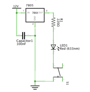
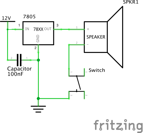
Circuit 1: Door Bell

  1. Components:  1) a 12 volt power supply: provide power for the whole circuit

                              2) a LM7805 Voltage Regulator: a transformer that expands the number of             components a single power can connect

                              3) a 100 nF Capacitor: to stabilize and smooth the flow of electricity in this circuit

                              4) a Speaker: make noise to see if the circuit is connected correctly

                              5) a Push-Button Switch: determine the connecting status of this circuit, creating interactivity

                              6) a Breadboard: a basic stage for building the circuit

2. Diagram:

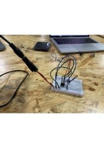
3. Pictures and video of the completed circuit:

4. The process of building: We insert the Voltage Regulator first between the positive and negative of the Breadboard. Then we put the Push-Button Switch into this breadboard with its different wires in two different rows. Then we connect the Speaker with one side to the switch and other side to the negative. The circuit worked perfectly as you can see in the video.

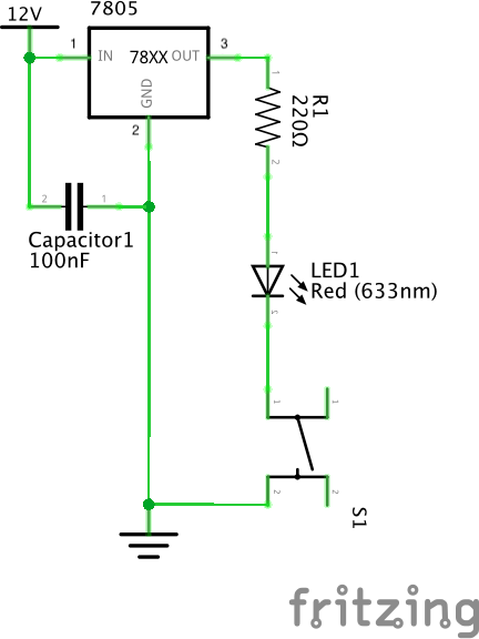
Circuit 2: Lamp

  1. Components: 1) a 12 volt power supply: provide power for the whole circuit

                            2) a LM7805 Voltage Regulator: a transformer that expands the number of             components a single power can connect

                            3) a 100 nF Capacitor: to stabilize and smooth the flow of electricity in this circuit

                            4) a LED: if connects with power, it can light

                            5) a 220 ohm Resistor: control the voltage so that the voltage for the LED will not be too much 

                            6) a Push-Button Switch: determine the connecting status of this circuit, creating interactivity

                            7) a Breadboard: a basic stage for building the circuit

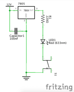
2. Diagram:

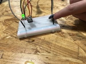
3. Picture and video of the completed circuit

IMG_2249

4. The process of building: Based on the foundation of the previous circuit of the speaker, it become slightly easier for us to build this circuit. We just change the speaker to the LED and insert a 220 ohm Resistor between the Voltage Regulator and the LED. We didn’t encounter any issues along the way, which is quite fortunate.

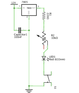
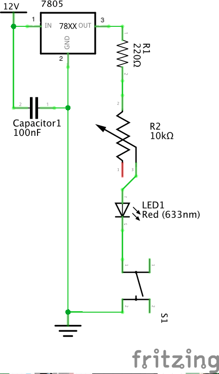
Circuit 3: Dimmable Lamp

  1. Components: 1) a 12 volt power supply: provide power for the whole circuit

                            2) a LM7805 Voltage Regulator: a transformer that expands the number of             components a single power can connect

                            3) a 100 nF Capacitor: to stabilize and smooth the flow of electricity in this circuit

                            4) a LED: if connects with power, it can light

                            5) a 220 ohm Resistor: control the voltage so that the voltage for the LED will not be too much 

                            6) a Push-Button Switch: determine the connecting status of this circuit, creating interactivity

                            7) a Breadboard: a basic stage for building the circuit

                            8) a 10K ohm Variable Resistor: to make the lamp dimmable

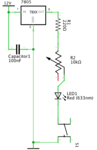
2. Diagram

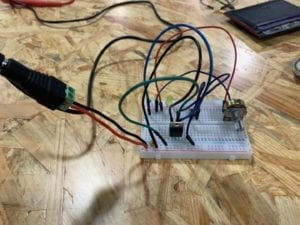
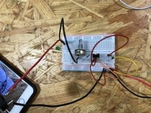
3. Picture and video of the completed circuit:

4. The process of building: Built on the foundation of the previous circuit 2, we just insert the variable resistor between the 220 ohm resistor and the LED. However, the circuit didn’t work first time we tried and the LED can’t be lighted. We then figured out the connection of the circuit was wrong since we connected the positive of the LED to the negative of the 220 ohm Resistor, and the variable resistor’s positive and negative were connected, making the circuit an open circuit. Then we corrected it and the circuit worked good as shown in the video.

Circuit 4: Switch the switches

1. Components: 1) a 12 volt power supply: provide power for the whole circuit

                            2) a LM7805 Voltage Regulator: a transformer that expands the number of             components a single power can connect

                            3) a 100 nF Capacitor: to stabilize and smooth the flow of electricity in this circuit

                            4) a LED: if connects with power, it can light

                            5) a 220 ohm Resistor: control the voltage so that the voltage for the LED will not be too much 

                            6) a soldered arcade button: determine the connecting status of this circuit, creating interactivity

                            7) a Breadboard: a basic stage for building the circuit

                            8) a 10K ohm Variable Resistor: to make the lamp dimmable

2. Diagram

3. Picture and video of the completed circuit:

4. The process of building: Based on the foundation of the third circuit, we just switched the push-button switch to the soldered arcade switch. Circuits worked great as shown in the video.

Questions:

1. From my perspective, the switch in the circuit is the core part of interactivity. Interactivity is defined as “a cyclic process in which two actors alternately listen, think and speak”. The definition shows that interactivity emphasizing on conversations between two entities. In the circuit that we build, the two entities should be people and the reacting item (either the speaker or the lamp). Human like us give out commend by clicking the switch, and the switch turns the open circuit to a closed circuit. Then the speaker start sounding and the lamp start lighting, delivering information we can perceive. Thus, the two entities have conversations and the key part of this conversation to exist is the switch.

2. Just as Zack Lieberman shown in the video. The interaction design and physical computing can      be used in many ways. The interactive painting Lieberman designed that allowed people to play with the whatever drawn in the screen suggests that interaction design can be used to stimulate inspiration in the artistic field. I also see the potential from this case that we can create lots of innovative and funny computer games for enriching our options for entertainment. The second case Lieberman showed in the video is the “Eye Tracker” to help those disabled artists to paint with their eyes. This innovation is really inspiring and significant since it brings up the idea of social responsibility. Trough interaction design and physical computing, we can make complex operations accessible to the disabled, leading to a brighter future for them.    

Recitation 1: Sensors by Tristan Murdoch

Tasks 1 and 2:

The goal of this project was to complete circuits to ring a doorbell (buzzer) and light an LED in different ways. This way, we gained a basic understanding of how circuits function, what to do, and what to avoid, such as short-circuiting.

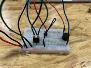
Below is an image of the first circuit we put together:

First Circuit

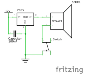
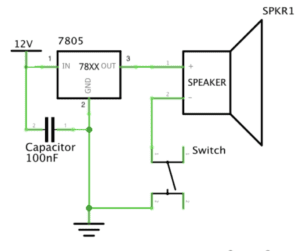
Included is a power source (supplying voltage) connected to a voltage regulator (to, well, regulate the voltage to the required amount).  A capacitor is connected to the voltage regulator to store voltage. The speaker is wired to the third leg of the voltage regulator, which is in turn connected to a button. From there it is connected to ground, along with the second leg of the voltage regulator. Components are held in place and connected by a breadboard.

Below are linked videos of the functioning doorbell, LED and dimmable LED circuits. The third video includes our own soldered button.

(Diagrams were already given to us for this recitation, so we decided not to include them in the post.)

In these circuits, the basics stayed the same (power source, capacitor, voltage regulator, and switch), but the speaker was replaced by an LED.  Furthermore, a 220-ohm resistor was used to limit the voltage the LED received. In the dimmable LED circuit a 10k-ohm variable resistor was used, allowing us to vary the amount of resistance, thus dimming or amplifying the light output.

Difficulties: For someone who has never touched a circuit before, the beginning was quite challenging. Connecting the capacitor to the voltage regulator took some time, but the diagrams helped greatly. The original button we used was also hard to understand. We were not aware that A/D and B/C were connected, but not to each other. A few times, our wires were not properly connected to the breadboard, causing us to think there was a complex problem while in fact we just needed to push the wires farther in. Other then that, everything went smoothly, soldering included.

Reflection:  Our project went exactly as planned with minor issues that we quickly solved. Building circuits gave me general, practical knowledge of how all the components work, but I still could not build one on my own without a directional diagram. I hope by repetition I can learn to understand how to build my own circuits for personal projects.

Question 1:  The author uses the terms, “listen, think and speak” to help define the word interaction. Take the LED circuit for instance: I press the button. The circuit “listens” processes what I asked it to do (with electricity) and “speaks” by illuminating the LED. I, seeing that the light is now on (listening), now want the light off (thinking), so stop pressing the button (speaking). 

But, I would argue that the interaction is minimal, based on the author’s definition. I can interact with the circuit, but it does send me instructions the same way I send it instructions. In this example, the circuit has no way of making me remove my finger from the button. 

Question 2: The fundamental part of interaction design and physical computing is that we can use it to make biologically non-living things react to our actions. The eye-tracking art feature in Lieberman’s video does just that. Another example is the wiring that allowed the reflective wood panel mirror to move in conjunction with a human’s movements to reflect light in the shape of what is in front of it.

Recitation 1. Circuit Basics by Eva

Recitation 1: Electronics & Soldering

Instructor: Marcela

Partner: Ally

Materials)

  • Breadboard – a device for temporary prototyping electronics as the layout allows easy access for making connections and experimentation in the production stages.
  • LM7805 Voltage Regulator – to maintain voltage output – a regulator is incorporated for sustainability of the Volt current. In this case, it allowed the 12V DC to be at 5V DC which would not blow the LED.
  • Buzzer – the output signal once pressed (input). For our circuit prototyping, it allowed us to confirm that the circuit was functioning.
  • Push-Button Switch – (can be input or output) let the electricity flow through the circuit.
  • Arcade Button – an alternative input element to the push-button switch. Serves the same purpose, with a different design. 
  • 220 ohm Resistor – The resistance that maintained our LED intact. An additional obstacle for the voltage to pass.
  • LED – light-emitting diode, served as output when circuit was functioning. 
  • 100 nF (0.1uF) Capacitor – for the LM7805 Voltage Regulator to be functional. 
  • 10K ohm Variable Resistor (Potentiometer) – With this resistor we were able to control the current going to the LED, thus being able to dim it and brighten it.
  • 12 volt power supply – The 220V AC was translated to 12V DC which was a safe Voltage for us to prototype and experiment on. 
  • Barrel Jack – were able to connect the power supply to the Breadboard with the Barrel Jack, (much like a plug power converter).
  • Multimeter – although contains many more options, we used the Multimeter to detect the appropriate resistor (of 220 ohm).
  • Several Jumper Cables (Hook-up Wires) – flexible, easy to plug in wires that worked very well in Breadboard connections for our circuits. 

CIRCUTS 

  1. Buzzer

Although fairly simple, this circuit was crucial in my foundational understanding of Energy and Ground. We specifically made sure to use the red jumper cable to connect the electricity flow to the buzzer component – to visually emphasise the concept of ‘power’. In addition, the black jumper cables were emphasising the connection to the Ground.

2. LED

Although we were pretty lucky in managing to find the correct corresponding holes on the Breadboard in the first circuit, the second one rose some challenges. In this phase, it was reiterated that the ‘legs’ of the LED are very specifically classified – the longer wire corresponds to positive/power, and the shorted leg corresponds to negative/ground. After we figured this out, we were able to switch around the LED and get the electricity running though the circus, thus allowing the LED to light up. 

3.  Dimmable Light

In this phase, we added a Potentiometer to customise the brightness of the LED. Although I cannot speak about the first attempt (as it was not successful), we decided to build it from scratch again.  I think this was an important aspect, because once we realised we cannot track the bug/error, we chose to not waste time in rebuilding each part of the circuit separately. I now reflect that we were able to do this as it is a still fairly simple design, which got me wondering how I would tackle such an issue on a larger prototype. How the two attempt might have been different? In this stage, I realised it was crucial to understand the logistics behind all of the components, because as we gained a greater understanding of the hardware we were working with (by the help of the fellows), the logical layout of the design made sense (in my head) thus it was more manageable to replicate it physically.

QUESTIONS

1. While reading “The Art of Interactive Design” I was able to differentiate between the concept of “interaction” and “reaction” (“It takes two people to have a conversation, and it takes two actors to have an interaction”). When thinking about the circuits we constructed, I applied the concept of the Degrees of Interactivity to better comprehend what our end-goal was. For example, when thinking about the buzzer – a button is pressed, therefore a sound is outputted – which I would consider a low degree of interactivity. The user does not have a choice of input, and there is only one possible output. In comparison, the addition of the Potentiometer allowed the degree of interactivity to rise – the user now has a choice of where to turn the ‘pointer’, and thus the output varies also. I also began to think how else this degree might increase in my future creations – the instructions – THE CODE. By customising the settings (both possible input and  output) the degree of interactivity rises. This really sparked my curiosity of “what else I can make happen”, especially in relation to Art and Design!

2. I currently began exploring how Artificial Intelligence  is used for style transferring when creating Art  [current favourite digital artist Gene Kogan]. I have never associated art with computers before University, so to start realising how well they interlink when creating is very motivating for an aspiring artist in the Digital Age. This emerging technological era just shows how tools like Interaction Design or Physical Computing can be customised to flourish creativity. I realise the power you gain once you learn the native language, in this case ( the instructions  through ) CODE in relation to the hardware. All of these tools aid us, but cannot do for us, therefore learning to follow an idea from initial stages of development to an end-product requires, not only diligence, but fundamental understanding of the “so-called place” you are creating in or with (online / Breadboard / robotics / etc). For Art to be Interactive, the artist has to know their direction they want to take with their audience  and the Digital Age tools serve as an accessible source for exploration of own ideas. 

Int Lab Recitation 1 Documentation by Daniel Chin

Writer: Daniel Chin 
Recitation partner: Linhui 
 
This is a write up for Interaction Lab SP18 Recitation on Electronics and Soldering on Feb 15, 2019. 

Components: what are they? 


Breadboard 

A pre-organized cable layout, easy to plug in jumper cables and other units’ legs. Good for organizing circuit. Good for when you want to start building a circuit but your mind is a blank. 

LM7805 Voltage Regulator 

Turns 12V DC to 5V DC. This, with the power supply, gives our buzzer and LED a friendly 5V. 

Buzzer 

Add direct current and it plays a 2200 Hz pitch. In our circuit, it is the output. It signals the user that the button is pressed. 

Push-Button Switch 

Use a finger to tell it whether to let current pass. 

Arcade Button 

A cooler Push-Button Switch. Acts as the input in our interactive circuit. 

220 ohm Resistor 

Add resistance. In our circuit, it alleviates some voltage off our LED, so that the LED won’t pop. 

LED 

Consumes electricity and emits red light. Very picky about which way the current goes. In our circuit, it is the output. 

100 nF (0.1uF) Capacitor 

To let the Voltage Regulator work. 

10K ohm Variable Resistor (Potentiometer) 

A resistor whose resistance we can control by rotating a disk. In our circuit, it controls the brightness of the LED. 

12 volt power supply 

Turns 220V AC to 12V DC. Today we plugged it into the wall and we have a safe voltage to play with. 

Barrel Jack 

The cable of the power supply doesn’t go into the breadboard. The barrel jack solves the problem. 

Multimeter 

Measures U, I, and R. We used it to find the right resistor. Also, as documented below, we used it to check for short circuit. 

Several Jumper Cables (Hook-up Wires) 

Cables that are easy to use with the breadboard. Makes building circuits as easy as drawing lines. 
 

The circuits 


Scheme of buzzer ↓ 
scheme of circuit 
 
buzzer working ↓ 


Scheme of LED ↓ 
scheme of circuit 
 
LED working ↓ 
 
 
Scheme of dimmable LED ↓ 
scheme of circuit 
 
Dimmable LED working ↓ 


Problems and how we solved them 


We encountered several problems during the recitation. 

1. Voltage regulator: which leg is which? 

We found the spec in recitation instruction webpage. 
 

2. Push-Button Switch: Four legs??? We only need two 

We asked Tristan. Problem solved. 
“Imagine they are claws.” Each claw has two fingers. The fingers of the same claw are connected. The button controls the connectivity between the two claws. 
 

3. Untitled 

Before plugging in, we checked for short-circuit with the multimeter on last time. 
It seemed to short! (The overall resistance of the circuit was 0) 
We checked the circuit and the current flow, and solved the problem. 
 

4. Untitled 

When final double checking, we found we missed a cable (from regulator IN to 12V). 
We added the cable. 
 

5. Oh no, we still got the legs wrong 

Circuit plugged in for 10 sec, Linhui reports abnormal smell. 
We detached power immediately. I found the voltage regulator very hot. 
We asked Leon. It turned out we got the voltage regulator spec perspective direction wrong. 
“Think about it as a chair. This is the back side of the chair.” 
We rotated the voltage regulator 180 degrees. Finally, the circuit worked as expected. 
 

Questions and my answers 


After reading The Art of Interactive Design, in what way do you think that the circuits you built today include interactivity? Please explain your answer. 

I think the circuits we built today provide feedback, but no interactivity is provided as is defined by The Art of Interactive Design. What we built are simple circuits, and are less interactive than the fridge example mentioned in the article. Here is why I think that. As defined in the article, interaction is the repeated process of “listen, think, speak” between two “actors”. In the fridge example, the “thinking” is simple, but the “speaking” is richer than the doorbell and LED we made today: When the fridge light powers on, the user sees the contents in the fridge, and that information input is way more dynamic and engaging than a simple LED. 
 

How can Interaction Design and Physical Computing be used to create Interactive Art? You can reference Zack Lieberman’s video or any other artist that you know. 

I personally believe that even a piece of writing, if good, can be interactive. Through carefully designed words, the writer can make the reader read, think, and respond to the text. Of course, the writing “thinks” too, and responds to the reader through the pre-determined but unpredictable chapters/paragraphs. 
 
The multi-model communication that Physical Computing offers only assist the good writing. Certainly, the power of real-time computing makes non-predetermined response possible, but any system, no matter how dynamic, requires “playwriting” or “designing” before the user steps into the picture. I think the quality of this playwriting is critical. 
 
For example, the game Undertale is highly praised for its integration of its relationship/emotion system and its combat system, but what I find interesting about Undertale is its character speeches. They are very smartly designed. It is good writing. Without good writing, assistive technology like an interactive gaming environment can never make an experience truly engaging. 
 
In conclusion, I think Interaction Design and Physical Computing are tools that open more options for expressing and listening, but to make something interactive, good playwriting is at the core. In the end, the creation only speaks for the creator. If the creator does not have something interesting to say, the creation would at most be a fancy toy.