Recitation 1 (Megan Rhoades)

Circuit 1: Door Bell

Parts: 

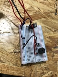
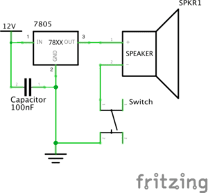
  • Breadboard: Provides a base for the connections in a circuit
  • LM7805 Voltage regulator: Controls voltage, allowing for consistent output
  • Switch: When pressed, connects the circuit to allow power to reach the speaker
  • Speaker: Vibrates, creating a sound, with the introduction of electric current
  • Jumper cables: Provide connections for the circuit
  • Barrel jack: Connects power supply to outlet
  • 100 nF (0.1uF) Capacitor: Stores (and helps regulate) electric energy
  • 12 Volt Power Supply: Provides power source

Process:

  • While this was the simplest circuit, we had to acclimate to using the components and building circuits. The biggest challenge for us in this aspect was figuring out the difference between the power and the ground, especially when connecting the voltage regulator. Finishing the circuit also provided some difficulty, as we were initially unsure of how power was flowing to the ground from the buzzer and switch. Moving on in the class, I know that I will have to put more effort into distinguishing which wires should be ground. Despite this confusion, we finished this circuit fairly quickly after getting used to the components. 

Circuit 2: Lamp

Parts: 

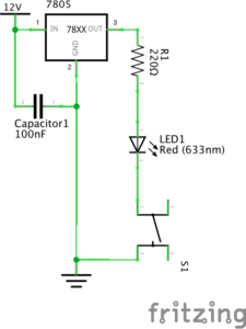
  • 220 ohm Resistor: Reduces current flow
  • LED: Emits light with electric current
  • Multimeter: Used to measure resistance

Process:

  • The most difficult process in this circuit was learning to measure the resistor with the multimeter. Since our fingers effect the reading of the multimeter, we asked for advice and found that measuring the resistor in between our fingers gave an accurate reading. After finding the correct resistor we simply made small adjustments to our previous circuit in order to add the LED and the resistor.

Circuit 3: Dimmable Lamp

Parts:

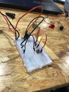
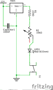
  • 10K ohm Variable Resistor (Potentiometer): Allows for interaction, with a turn of the dial adjusting the strength of the electric current

Process:

  • This circuit was the easiest of the three. After adjusting the position of the light, we simply added the variable resistor. I did feel that I learned something from observing the interactivity of the resistor — this technology is basic yet I had never put thought into how it works. For that reason, this circuit was the most interesting to us. 

Push-Button Switch

Process:

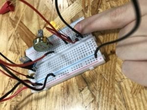
  • After finishing circuit 3, my partner and I disassembled our circuit. For this reason, we had to reassemble the circuit for the inclusion of the new button. We had some difficulty with this new circuit. Again, we found ourselves confused with the difference between ground and power. We also found ourselves debating ways in which we could cut down on the number of jumper cables, simplifying our circuit. Although we had some difficulty we did eventually create a new circuit and I found the process useful in practicing the building process.

Question One

The interactivity reading introduced the idea that interactivity comes on a spectrum. This felt very clear to me thinking on the different circuits we built in recitation. The third circuit, which included a dimmable light, felt more interactive than those which had only a switch. Although all required action from a human (the press of the switch) to operate, this circuit was more responsive, giving not only the option of on/off but also the ability to control how much light was emitted. 

Question Two

As someone who is very interested in music, there are many interesting interactive possibilities. One idea that I have seen in an exhibit in my hometown in Ohio is an orchestra made of “electric instruments” — one example being a harp which sensed the movement of a human finger in a certain place and played the correct tone in response. I think this idea could be developed to help disabled musicians, similar to the EyeWriter being used to allow a disabled graffiti artist do his work. These examples which combine human creativity and electronic tools are especially interesting to me.  
Electric Circuits, Electrical Components and Interaction – Monika Yosifova Response

My experience in my first ever Interaction Lab Recitation was not what I expected. I didn’t know that there were so many people taking that class and it was truly exciting to actually get to meet new people. The girl that I was working with on the electric circuits project is called Tiana, and we both worked really hard to understand how both soldering and building circuits operated!

Circuit 1:

For the first circuit we used a Breadboard to help us organise our electric circuit. We connected this breadboard to a 12 V power cable which was the source of electricity for this circuit. We connected the red cable from that 12 V Power supply to the positive charged slots on the breadboard and the black cable we connected to the Negatively marked slots on the breadboard. This made everything that was connected to the Negatively charged slots ground. Then Tiana and I plugged in the Voltage regulator in the breadboard, it controlled the amount of power output throughout the breadboard. We connected sections 1 and 2 of the Voltage regulator together with a 100 nF Capacitor which condensed and stored some of the energy throughout the circuit. I then used a black cable to connect section 2 of the voltage generator to ground. Managing to get the Switch Button to work was more difficult as we had to watch the placement for it more carefully. We made a few mistakes with it’s placement and needed help figuring it out. Lastly, we put in the Speaker, plugging it in with energy from the 3rd slot of the Voltage Regulator. When we pressed the Switch Button after we plugged the circuit into the power, we heard a rather loud “WOOOM” sound and we celebrated.

Note: We originally hadn’t plugged the Voltage Regulator in and were wondering why it wasn’t working. We were being too careful with it cause we though we’d break it.

Circuit 2:

Circuit 2 personally gave me the most satisfaction to make. I love lights and as someone who never studied physics before, it was always amazing for me to see how people made a light turn on. When Tiana and I managed to get Circuit two done correctly, with no help, I felt like a Air-bender or a wizard (only for electricity). 

Similarly to circuit 1, our group utilized the Breadboard, the 12V power source, the Voltage Regulator and the capacitor  in a  way similiar to before. Section two of the Regulator was plugged into ground while section one was plugged into  power. The Capacitator was again used to connect Sections 1 and 2.  It got more interesting once Tiana and I had to figure out which resistor to use. We had been provided with two and had a difficult time finding out which one was the best. Professor Cossovich came over and explained the color-coding on the little resistor to us and we were good to go. This 220 Ω  resistor reduced the flow of electricity along the circuit and we connected it to one end of the little yellow LED light bulb that we were supposed to turn on.  Tiana then put in the Switch button, connecting one of the ends of it to ground while the other one was connected to the LED. Once we pressed the Switch, the little light turned on.

Circuit 3: 

Circuit three was by far the most complicated, but after being able to successfully make the previous two circuits, Tiana and I were really excited and just got on with the job. Class had already ended, but we were so curious about what the next little challenge was that we just wanted to construct it.

Similarly to the last two circuits, we utilized the Breadboard, the 12V power input, the Voltage regulator and the Capacitor, connecting Section two with the Capacitor to ground. Section 1 of the Voltage Regulator was connected to Power. Section three we connected to the 220 Ω Resistor again, with red cables, and then we connected it to section two of the Potentiometer. The potentiometer allowed for more control around the circuit as we connected its third section to the Led light. The LED light we then connected to the Switch Button again. There was a black cable that connected ground to the Switch on the other end. When we connected the circuit to the power, the LED automatically switched on, which was a mistake. Professor Cossovich then told us that we had, again, plugged in the Switch Button wrong.  After fixing that, the circuit worked!

Responding to Question 1:

I really had a laugh with some of my friends after reading “The Art of Interactive Design” article.  I though it was an engaging read. 

The circuits that we build in the Friday Recitation class were highly interactive as they created a level of concentration among the pairs that were building them. I had never worked with Tiana before, but the two of us were listening to each other, thinking about how to make the circuits work and communicating what we though was the correct way. It was a good project that brought me closer to someone I never honestly thought I’d work with, and I enjoyed it a lot! 

Responding to Question 2:

Interaction Design and Physical Computing be used to create Interactive Art in many ways. People get shocked and impressed by little things, an example for that would be the “Open Mouth” idea that Zach Lieberman explains to us when he presented his interactive music art to other people. Physical computing and Interaction design, if used correctly and coded properly can revolutionize art and expand people’s imagination and belief of the possible. I know it sounds cheesy, but I like to make people happy, and art that is produced in a way that the audience can interact with it always pleases people. 

Thank you for an awesome first week!

Monika V. Yosifova