Recitation 1: Electronics and Soldering by Like Yang

Circuit 1: Door Bell
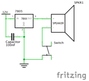
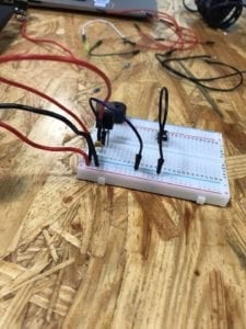
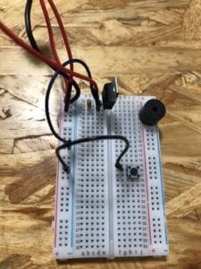
Picture of Door Bell
Circuit 1: Door Bell

Components:

1 * Breadboard – This is the base for us to connect all the other electrical components together without soldering. There are also connections within the breadboard that we can make use of.

1 * LM7805 Voltage Regulator – To make sure that the current went into the circuit is smooth, we need a voltage regulator so that the buzzer would work. Also, may work with the capacitor to protect other components (LED, buzzer) if there is a sudden blackout.

1 * Buzzer – This component can make sound if connected to electricity. Shall be viewed as the central component of a door bell.

1 * Push-Button Switch/ 1 * Arcade Button – They are two different kinds of switches that can control whether there is electricity in the circuit.

1 * 100 nF (0.1uF) Capacitor – In this circuit, it is the same as a resistor that has an infinite amount of resistance so as the voltage regulator could be connected to ground. Also, the electricity stored in the capacitor may help to protect the LED or buzzer if there is a sudden blackout.

1 * 12 volt power supply – get power from the socket.

1 * Barrel Jack – connect the whole breadboard with the 12v power supply.

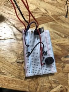
Pictures of the Circuit:
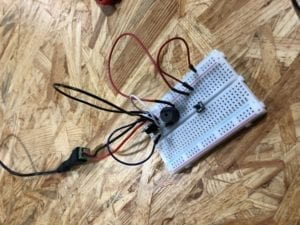
Circuit 1
The first kind of door bell
door bell 2
The second kind of door bell

Process:

It is always very difficult to start doing something that I am unfamiliar with. In fact, I have never seen breadboards and never finished a circuit like this before. At the very beginning, my partner and I even thought that we did not need to use electric wires if we put everything on a breadboard since there are built-in connections. However, we immediately realized it was a mistake. After getting more wires, we stuck on the installation of the voltage regulator and capacitor. We tried to connect them via wires but it turned out that we could use the built-in circuit inside the breadboard. To tell the truth this is confusing because we were unsure how to make use of the connection within the breadboard. The next difficulty we faced is the switch. It was really hard to understand why the switch has four pins instead of two before Nick introduced the design of the switch. Anyways, after encountering so many problems, our circuit finally worked and the process of changing the switch into an arcade button went on smoothly since we have already got some sense of building a circuit.

Circuit 2: Lamp
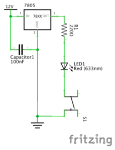
Picture of Lamp
Circuit 2: Lamp

1 * Breadboard – This is the base for us to connect all other electrical components together without soldering. There are also connections within the breadboard that we can make use of.

1 * LM7805 Voltage Regulator – To make sure that the current that went into the circuit is smooth so that the LED would work. Also, may work with the capacitor to protect other components (LED, buzzer) if there is a sudden blackout.

1 * Push-Button Switch – control whether there is electricity in the circuit.

1 * 100 nF (0.1uF) Capacitor – In this circuit, it is the same as a resistor that has an infinite amount of resistance so as the voltage regulator could be connected to ground. Also, the electricity stored in the capacitor may help to protect the LED or buzzer if there is a sudden blackout.

1 * 12 volt power supply – get power from the socket.

1 * Barrel Jack – connect the whole breadboard with the 12v power supply

1 * 220 ohm Resistor – To reduce the voltage connected to the LED and avoid damage.

1 * LED – give out light after electricity flows into the circuit.

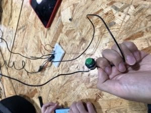
Pictures of the Circuit (My index finger is where the switch was at):
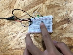
Picture of Lamp
Picture of Lamp

Process:

The process of building a lamp is much easier because we have already built the foundation when building the first circuit. We just need to change the buzzer into a LED light. However, it is important to notice that the positive and negative poles of the LED. The longer pin represents the positive pole and we need to follow the right direction to successfully light it up.

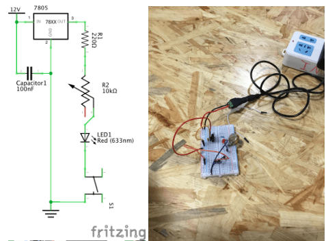
Circuit 3: Dimmable Lamp
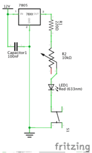
Picture of Dimmable Lamp
Circuit 3: Dimmable Lamp

1 * Breadboard – This is the base for us to connect all other electrical components together without soldering. There are also connections within the breadboard that we can make use of.

1 * LM7805 Voltage Regulator – To make sure that the current that went into the circuit is smooth so that the LED would work. Also, may work with the capacitor to protect other components (LED, buzzer) if there is a sudden blackout.

1 * Push-Button Switch – control whether there is electricity in the circuit.

1 * 100 nF (0.1uF) Capacitor – In this circuit, it is the same as a resistor that has an infinite amount of resistance so as the voltage regulator could be connected to ground. Also, the electricity stored in the capacitor may help to protect the LED or buzzer if there is a sudden blackout.

1 * 12 volt power supply – get power from the socket.

1 * Barrel Jack – connect the whole breadboard with the 12v power supply

1 *  10K ohm Variable Resistor (Potentiometer) – This resistor allow us to adjust the resistance so as to control the lightness of the LED.

1 * LED – give out light after electricity flows into the circuit.

Pictures of the Circuit:
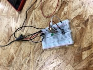
Picture of Dimmable Light

Process:

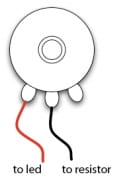
To convert circuit 2 into circuit 3, we only need to change the resistor into a potentiometer. But initially I did not know why the potentiometer has three pins. I happened to connect the two pins that are seprarated from each other into the circuit and the LED was not on. Later, after receiving some instructions, I found out that I should connect to the two pins on the left and in the middle. In that case, when I rotate the potentiometer, the lightness of LED would change.

Answer for Reflection Question 1:

According to the author, we should define interactivity as “a cyclic process in which two actors alternately listen, think, and speak.” From my perspective, the interactivity of the circuit we built comes from its response when we press the switches. When we implement such an action, the circuit receives a signal. In other words, this is what it could ‘hear’ from human beings. We could hardly say that there is a process of ‘thinking’ within the circuit but after it receives the signal, it answers by turning on the whole circuit and lighting up the LED. I regard this as a way for it to ‘speak’ with us. I think this entire process has met the author’s criteria for interactivity. What is more, for green hands like us to build a circuit often needs communication with others. It would be unlikely for us to complete a circuit solely from the materials on our table. When we have conversations with others about our thoughts on the circuit, this includes interactivity as well. So, I think the circuit itself and the process of building includes two different levels of interactivity but they are both inspiring.

Answer for Reflection Question 2:

In my opinion, there are two ways that physical computing and interaction design can be used to create interactive art. One method is to use physical computing to expand the existing forms of art so that we could see artworks that we would not be able to. An example for this is ‘The Eyewriter.’ The engineers created a method that could help an artist who could not move his body to continue creating graffitis. In terms of art, the work we see is essentially graffiti but the production process involved the intelligence of interaction design and physical computing. Another way that interaction design and physical computing can creat interactive art is to come up with completely different forms of art such as the ‘wood mirror’ that could capture people’s movements by changing colors. Without the help of technology, even if artists have the materials to present the idea, the visual effect and artistic value would not be as good as the one we saw in the film clip. In other words, physical computing helps many artists to put their imagination into reality to the best extent and help them better express their ideas.

Recitation 1: Electronics and Soldering By Tiana Lui

Author: Tiana Lui, Class: Interaction Lab, Professor Cossovich

2.15.19

Components of the circuits: what they do and why are they included

1 * Breadboard- this is where the circuit is connected by wires. The breadboard connects components of a circuit together. A completely connected circuit is necessary for the circuit to work.

1 * LM7805 Voltage Regulator- Voltage regulators maintain a constant voltage level. They are important because many electronic devices only work properly within a certain range of voltage, and voltage regulators can make sure the voltage supplied in the circuit stays within that optimal range.

1 * Buzzer- A buzzer is an electrical device that converts one type of power to audible sound. 

1 * Push-Button Switch- Switches are a control that can be used to interrupt the flow of current through a circuit. A pair of contacts within the switch are connected or disconnected depending on the physical position of the switch. When connected, the circuit is complete, and can execute tasks. When disconnected, the circuit is unattached, and the electronics do not execute anything.

1 * Arcade Button- Another type of switch.

1 * 220 ohm Resistor- A resistor is a two-terminal electrical component that resists the flow of electricity, and can be used to control the flow of current.
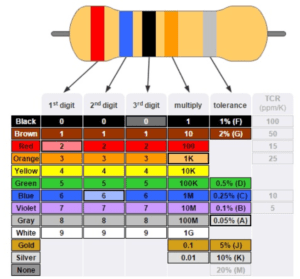
Resistors are marked with a series of colored stripes which indicate their amount of resistance.

1 * LED- Light-emitting diodes are a type of diode which can act as a visible or invisible light source. They are frequently used as indicator lamps in many electronic devices, or collectively as a display.

1 * 100 nF (0.1uF) Capacitor- Capacitors store electricity while current is flowing into them, then release the energy when the incoming current is removed. Capacitors can also be used to stabilize and smooth the flow of electricity.

1 * 10K ohm Variable Resistor (Potentiometer)- A resistor with the ability to change and control how much resistance to electrical current that programmer wants.

1 * 12 volt power supply- The power supply provides the power for the circuit to conduct electricity.

1 * Barrel Jack- Barrel jacks are electrical power connectors used for attaching extra-low voltage devices such as consumer electronics to external electricity. This is needed because we need a way to connect our circuit to power in order for there to be electricity/power to make the circuit run. 

1 * Multimeter- Multimeters can measure the current, voltage, and resistance of objects. They are useful for identifying the correct components with the correct current, voltage, and resistances to place into your circuit. 

Several Jumper Cables (Hook-up Wires)- Wires connect the circuit together. Without wires, electronic components are detached and the circuit is unable to work, because only a completely connected circuit will work.

Diagrams of the circuits

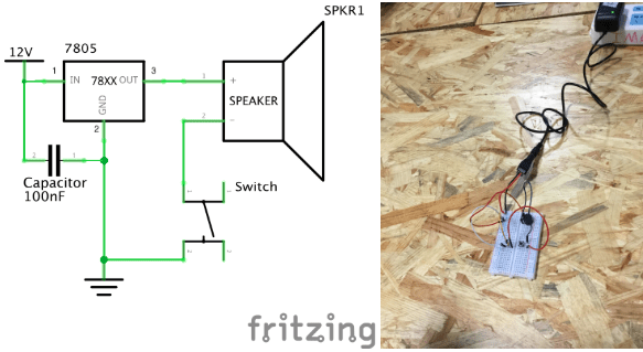
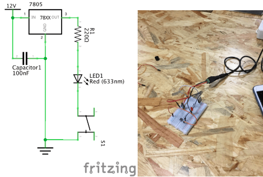
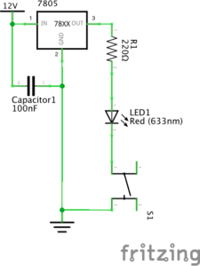
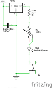
Below are the schematics of the circuits we built. The first one is a doorbell circuit, the second is a circuit of an led lamp, and the final circuit is a dimmable lamp circuit. 

doorbell

lamp

dimmable light

My notes

This was the first class we used the breadboard.

Initially, the breadboard was confusing to use, because we didn’t know what wires went where.

The picture of how the breadboard works helped us (the breadboard is composed of two strips of metal on the side and rows of metal on the inside).

We found out how to translate the circuit drawing to the breadboard.

So, to translate drawing to circuit, identify power source (12v this time).

Tip: keep power source wires on the side of breadboard (on the two vertical metal strips)

In this case, power source has two wires, one for power and one for ground

Continue connecting things to those immediately next to it in the drawing

If in the drawing, something is next to ground, connect component to ground on breadboard.

If in the drawing, something is adjacent to both power source and ground, connect component to both ground and power source.

Voltage regulator had a 3 pins, and the order in which it was connected to other components mattered. The way to distinguish the pins is to understand that the bulky part (package) was the front. Knowing this made it easy to identify the order of the pins that corresponded to the drawing.

Keep the capacitor close to the voltage regulator. For some reason, the circuit will work better this way. Why?

Make sure the buzzer is in line with your wires. The buzzer is bulky and bigger than the width of the pins you input, so make sure to check that you put your wires next to the pins.

Tip: keep the buzzer slightly tilted/not all the way in to double check the positionings of its pins so you can accurately place wires next to those pins

There are different ohm resistors. You can check their color codes or use the multimeter to measure their ohms. color codes for resistor

The multimeter reading didn’t work for us as the number kept jumping around. Need to understand how to properly get a multimeter reading. Also need to keep in mind conversions between units (ie. ohms and kiloohms)

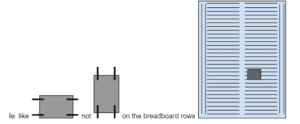
The switch has an orientation. It should be placed horizontally, (longer side connects on same row)

Picture of correct and incorrect orientation of switch on breadboard

Unplug the power source every time before you move wires around, otherwise components can get fried and damaged.

We were only able to complete 2 circuits. We didn’t test out the push button we soldered.

Soldering (pretty straightforward)

There’s a machine that controls the temp of pen and makes a pen super hot, a stand for your soldering pen which has a cleaning sponge to clean the pen, metal wire you melt onto the two things you want to connect, a wire stripper, wire cutter…

The pen thing just gets really hot so you can melt metal.

Always clean pen (stab it on the sponge) to preserve its longevity and prevent rust.

A good solder is even and connects the two places you want to connect

Strip a bit of the end of wire, connect it to other part, solder by melting wire with pen, the melted metal should touch both exposed wire and other part.

Don’t breathe in fumes, they are toxic

Aren’t we supposed to have masks and some sort of vent/fan that captures/draws away the toxins???

Other advice

Most times, if circuit is good, double check the position of your capacitor?

Pictures and Video Captures

doorbell circuit completed doorbell circuit WIP doorbell circuit WIP

LED lamp circuit

Question 1:
After reading The Art of Interactive Design, in what way do you think that the circuits you built today include interactivity? Please explain your answer.

According to The Art of Interactive Design (Crawford), there are low and high levels of interaction. Since the circuits we built on Friday were relatively simple and only performed one task upon execution/under our influence, the circuits could be considered low-level interaction. However, the code and time required to build these circuits are much more complicating, and so our interaction with the circuits are relatively high and long. It is very challenging to define whether something is interactive or not, as there is no consensus on the scope of interaction. Does opening the refrigerator count as interaction, or does it count as talking to a brick wall? Does interaction only count when there is feedback both ways? And what type of feedback is qualified to be “interactive”? These are questions that need to be answered first before anything can be defined as interactive or not.

That said, the circuits we built on Friday, have various instances of interaction. For example, a human finger (analog input) pressing a button, causing the circuit to connect and complete. Or, the breadboard circuit communicating with the computer/arduino software, causing the electronics to execute actions. We also interacted with the hardware, placing wires into the breadboard, however, in that moment, the breadboard was not attached to the computer, hence, the breadboard gave no feedback, and may not count as interaction. We also interacted amongst ourselves, communicating with each other on how best to build the circuit. Above are examples of interaction, where two things that came in contact with one another produced some sort of action or communication.

Question 2:
How can Interaction Design and Physical Computing be used to create Interactive Art? You can reference Zack Lieberman’s video or any other artist that you know. 

Interaction is about two or more things connecting, and communicating something to each other or spurring some sort of action to be executed. Physical computing is great for interactive art because physical computing is about making an electronic device communicate with computer software to perform some sort of action, a process that is already interactive. Interactive art using physical computing is also scalable, in the sense that the programmer can start by programming a low-level interaction, then move on to coding more complex interactions, generating higher-level communication and engagement between the computer, user, and artwork.

Physical computing can be combined with any type of interest to form an interdisciplinary study, so it is not unusual that physical computing is combined with art. One such artist, Zach Lieberman uses interactive media to explore the relationships between technology, performance, and the body. He has created projects including an open-source eye-tracking system that allows disabled artists to draw using their eyes, and a performance that includes drawn sketches that react to a visitors’ touch. 

In summary, the world is your oyster. It is up to your imagination to use physical computing to create interactive art.

Documentation 1 – Kathy

Circuit 1: Doorbell

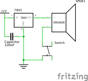
List of Components:  Wires, Power cord (12V), Breadboard, Capacitor (100nF), Voltage Regulator 78XX, Switch, Speaker,

  • The wires are used to connect the components together.
  • The power cord gives the breadboard power by connecting to electricity.
  • The breadboard allowed us to make the electrical circuit.
  • The capacitor holds excess electricity and stores it for future use. It does not dissipate energy and provides a consistent voltage which improves the performance of the circuit.
  • The 78XX is a voltage regulator, it is included to produce a voltage that is positive relative to a common ground
  • The switch turns the doorbell on.
  • The speaker is included because it acts as a doorbell; it is the output.

The circuit worked the first time we built it, however, we forgot to include the voltage regulator. We were also unsure about the orientation of the switch. After a couple of rotations, we realized that it best bit between the gaps of the breadboard.

Circuit 2: Lamp

List of Components: Wires, Power cord (12V), Breadboard, Capacitor (100nF), Voltage Regulator 78XX, Switch, Resistor (22 Ohms), LED (633 nm)

  • The wires are used to connect the components together.
  • The power cord gives the breadboard power by connecting to electricity.
  • The breadboard allowed us to make the electrical circuit.
  • The capacitor holds excess electricity and stores it for future use. It does not dissipate energy and provides a consistent voltage which improves the performance of the circuit.
  • The 78XX is a voltage regulator, it is included to produce a voltage that is positive relative to a common ground.
  • The Switch turns the LED light on.
  • The resistor is used to limit the amount of current going through the circuit. If a resistor is not included the LED can be destroyed
  • The LED light lights up.

The LED light did not work the first time we set it up. This is because we did not know how to include the voltage regulator into the breadboard along with the resistor. We found it kind of confusing to put them together. We figured out that we had to use the resistor as the connector between the voltage regulator and the LED light as there would be not enough space on the board if we used wires.

Circuit 3: Dimmable Lamp

List of Components: Wires, Power cord (12V), Breadboard, Capacitor (100nF), Voltage Regulator 78XX, Switch, Resistor (22 Ohms), LED (633 nm), Potentiometer (10k Ohms)
  • The wires are used to connect the components together.
  • The power cord gives the breadboard power by connecting to electricity.
  • The breadboard allowed us to make the electrical circuit.
  • The capacitor holdsexcess electricity and stores it for future use. It does not dissipate energy and provides a consistent voltage which improves the performance of the circuit.
  • The 78XX is a voltage regulator, it is included to produce a voltage that is positive relative to a common ground.
  • The Switch turns the LED light on.
  • The resistor is used to limit the amount of current going through the circuit. If a resistor is not included the LED can be destroyed
  • The LED light lights up.
  • The Potentiometer is a multi-terminal resistor or a “voltage divider”. It is included to dim the light in the LED.

While building the dimmable lamp, we had trouble attaching the potentiometer to the breadboard. Since there were three pins attached to the potentiometer, we had trouble understanding what each pin was used for. The first time we built the dimmable lamp it did not work, only the LED turned on. After changing around the orientation of the wires and correcting connecting the LED and the resistor to the potentiometer, the LED successfully dimmed.

Reflection

Question 1: After reading The Art of Interactive Design, do you think that the circuits you build today include interactivity?

After reading The Art of Interactive Design, I believe that the circuits I built today included interactivity. Together, my partner Serene and I thought about how to connect the objects together to create a circuit. Whenever there was a problem, we examined the circuit, and listened to one another’s ideas about what could have went wrong. We also interacted with the objects that we had and created the output of sound and light out of small electrical components which is pretty fascinating.

Question 2: How can Interaction Design and Physical Computing be used to create Interactive Art? You can reference Zack Lieberman’s video or any other artist that you know.

Interaction design and physical computing could be used to create interactive art through the use of coding, technology, and physical art. In Zack Lieberman’s video, he created a Eyewriter which ultimately lead to an type of interactive art. The idea behind the Eyewriter was interactive between the patient and the world outside of the hospital creating a magical performance for the patient and the people outside. With interactive design and physical computing, the power of coding, technology and a purpose for the creation, the art, design, and technology together merge into interactive art.

Interaction Lab-Recitation 1 (Ning Zhou)

Circuit 1: Door Bell

Components:

1*Buzzer: Creates sound with electric current flow. 

1*100 nF Capacitor: Stores electric charge.

1*Switch: Builds or breaks the connection in the electric circuit.

1*LM7805 Voltage regulator: Transfers the voltage level. Used to transfer 12V into 5V in our circuit.

1*12volt power supply: Provides 12volt power for our circuit.

1*Breadboard: A base board for us to build the model of electric circuit.

Several jumper cables: Build connection between components in the circuit.

1*Barrel jack: Connect the power supply and the circuit.

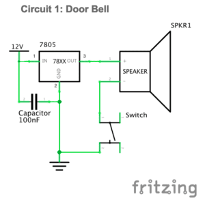
diagram

video:

Process: 

My partner Amily and I both knew little about building an electric circuit. So, we just followed the given diagram of the circuit and the instructions of the components at first. The speaker didn’t make any sound when I pressed the switch. Then we asked Jingyi for help. It turned out that we made several mistakes. One of the problems is that we set the ground and power wrong at the beginning, which is a big problem because many components need to be connected to the ground. Also, the directions of the current flow in the breadboard are different for the parts in the middle and the other parts on two sides. Another thing is that the switch with four legs is self-connected between the two diagonal legs, not the parallel legs. After figuring out these, we rebuilt the circuit and it worked this time.

Circuit 2: Lamp

Components:

1*220ohm Resistor: Provides resistance and opposes the flow of electricity.

1*LED: Emits light with electric current flow.

1*Multimeter (missed): Used to measure resistance.

1*LM7805 voltage regulator,1*switch,1*100 nF capacitor,1*12volt power supply, several jumper cables,1*barrel jack,1*breadboard.

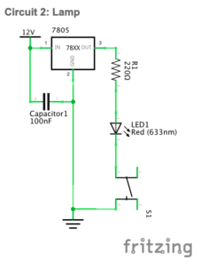
diagram:

video:

Process:

After the practice of the first circuit, Amily and I were clearer about each component’s function and how to connect them in the circuit. One thing we missed is that we forgot to connect the multimeter because we just focused on the diagram of the circuit in which the multimeter is not shown. We were not aware of this until we turned it in at the end of the recitation. But the circuit still worked well.

Circuit 3: Dimmable Lamp

Components:

1*10K ohm Variable Resistor (Potentiometer): Provides variable resistance to oppose the flow of electricity. It can change the brightness of the LED in the circuit.

1*Breadboard,1*220ohm resistor,1*LM7805 voltage regulator,1* switch,1*LED,1*100 nF capacitor,1*12volt power supply,1* barrel jack, several jumper cables,1*multimeter (missed).

diagram:

video:

Process:

The circuit is similar to the second circuit so we built this one quickly. It didn’t work at first. We then found that there was a small problem of the connection of variable resistor. The middle branch should connect to resistor. We fixed this and made the circuit work. The brightness of the light changed accordingly when we rotated the variable resistor. We forgot the second task of switch the switches. Both of us missed the instructions for this part and simply thought that we only had the task of building the three circuits. To replace the push button, we can just take it off and leave the jumper cables as the same. Each jumper cables of the arcade button should be set in the same row as one of the other jumper cables left on the breadboard in order to allow the current flow.

Soldering task:

Reflection: My partner and I encountered many problems in our first recitation. We also missed some steps for our tasks. But after this recitation, both of us became more familiar with different components and the structure of circuits. More importantly, I learnt the lesson of doing preparation before class and paying more attention to the materials and instructions. Also, the sense of achievement that a successful circuit gives is awesome.

Question1:

After reading The Art of Interactive Design, in what way do you think that the circuits you built today include interactivity? Please explain your answer.

I think that the circuits we built include interactivity because they reacted to our actions. But I do not consider the action between the circuits and us as interaction. Similar to the refrigerator situation, when I press the button, they listened (to the pressed button), thought (with electric current through the circuits), and spoke (by creating sounds or emitting lights). These are the input, process, and output. The third circuit seemed to be more interactive than the other two because it can react to different actions accordingly. However, in all of the simple interactivity, we design the other actor so that we can predict their exact response. They are not actually thinking. What they do is mechanical process that built by us.

Question 2:

How can Interaction Design and Physical Computing be used to create Interactive Art? You can reference Zack Lieberman’s video or any other artist that you know.

In my opinion, interaction design and physical computing are both of great importance in interactive art. Interaction design is more like an inspiration while the physical computing is the process that transforms the theory into reality. Zach said that art is a form of research. I think that only during the process of conducting research could people find problems and then to create something new to solve the problems. In his third interactive art, Zack Lieberman together with other artists sought to create a new form for disabled graffiti artist to draw again. This is something that inspired them. Later by physical computing, they made their idea come true, and also made Tony’s come true. Being paralyzed could be considered as being largely disconnected to the outside world. The eye-writer enables Tony to build interactions again. One of my friends likes graffiti as well. Once I went out with him, watching him drawing on the wall. I felt like for them, the meaning of drawing is much about tagging, showing, sending messages and interacting with others with their drawings. So, I think that these values were acknowledged by Zach’s team and inspired their design.

Interaction Lab-Recitation 1 (Serene Fan)

Circuit 1-Door Bell

Components:

1*Breadboard:  A base for connecting components

1*LM7805 Voltage Regulator:  To regulate and maintain a constant voltage level which is suitable for the circuit

1*Push-Button Switch: Able to connect the whole circuit when it is pressed

1*Buzzer: To output an audio signal

1*100 nF (0.1uF) Capacitor: To store electrical energy

1*12 volt power supply: To provide power source

1*Barrel Jack: An electrical connector for supplying direct current

Jumper Cables (Hook-up Wires): To connect components

The Diagram

The Building Process and Problems We met

How to connect the switch???  

When we were connecting the switch, we found it difficult to distinguish which two feet to choose. We expected there should be different length of the feet so that we could identify the anode and the cathode, but all the four feet seemed the same. Out of ideas, we turned to Nick for help. He then told us the way of connecting the switch was to  know that foot A and D are always connected. Same with foot B and C. Therefore, only connecting either A or D to either B or C can be counted as successful connecting.

Where is the voltage regulator???

We first built the circuit without the voltage regulator, because we misinterpret the symbol for the voltage regulator as the power source. Since the circuit still worked well, we did not notice this mistake. However, Leon came by and pointed out that we should add the voltage regulator to the circuit in case the voltage level could be too high for it. Therefore, we corrected our circuit and it worked again. 

Circuit 2-Lamp

Components: 

1*Breadboard:  A base for connecting components

1*LM7805 Voltage Regulator:  To regulate and maintain a constant voltage level which is suitable for the circuit

1*Push-Button Switch: Able to connect the whole circuit when it is pressed

1* Arcade Button: Able to connect the whole circuit when it is pressed, but needed to be soldered

1*220 ohm Resistor: To reduce current flow

1*LED: Able to emit light when connected to the power source

1*100 nF (0.1uF) Capacitor: To store electrical energy

1*12 volt power supply: To provide power source

1*Barrel Jack: An electrical connector for supplying direct current

Jumper Cables (Hook-up Wires): To connect components

1*Multimeter: To measure voltage, current and resistance

The Diagram:

The Building Process and Problems We met

Why the light was not on???

We built the circuit exactly as what the diagram told us, however, the LED just refused to emit light. We checked every connecting point without recognizing any problem. At last, we asked Nick about this situation. As he suggested, we used the multimeter to measure the resistance and surprisingly figured out that we connected the wrong resistor, which was only 10 Ω. We immediately altered the resistor and the light went on.

We replaced the switch!

After soldering the arcade button, we decided to replace the push-button switch. The process was quite simple. And we found that there was no need to take down the push-button switch while connecting the arcade button.

Circuit 3-Dimmable Lamp

Components

1*Breadboard:  A base for connecting components

1*LM7805 Voltage Regulator:  To regulate and maintain a constant voltage level which is suitable for the circuit

1*Push-Button Switch: Able to connect the whole circuit when it is pressed

1*220 ohm Resistor: To reduce current flow

1*10K ohm Variable Resistor (Potentiometer): To change the resistance in a close circuit

1*LED: Able to emit light when connected to the power source

1*100 nF (0.1uF) Capacitor: To store electrical energy

1*12 volt power supply: To provide power source

1*Barrel Jack: An electrical connector for supplying direct current

Jumper Cables (Hook-up Wires): To connect components

1*Multimeter: To measure voltage, current and resistance

The Diagram

The Building Process and Problems We met

Why the light was not on again???

Again, we followed the diagram but found the light was not on in a close circuit. Based on experience, we checked the resistor and were sure it was the right one. What confused us was that the first time we pressed the button, the light was on perfectly. However, every time we pressed the button, the light became dimmer until it vanished completely. We were afraid that we might have burnt the light for some unknown reason, so we asked Marcella for help. She checked our circuit and told us we connected the variable resistor in a wrong way. 

As the picture above shows, we then connected the left and the middle terminals into the circuits. It turned out that the circuit worked well and we did not burn the LED.

Reflection

The diagrams were simple enough to understand and the building process was quite easy. However, we still met problems. After the solutions were figured out, I reflected on why these problems have come up. One reason was that we did not read the instructions carefully enough to clearly know how to connect every components. Another reason was that we were not familiar with the breadboard, which made us panic easily every time there existed problems. For solutions, I found a helpful piece of reading in the instructions for this recitation called “Getting Started in Electronics”, through which I could access detailed basic knowledge of electronics. 

Answers to the questions

Question 1:

After reading The Art of Interactive Design, do you think that the circuits you built today include interactivity? Please explain your answer.

According to The Art of Interactive Design, there is no absolute answer to the question of whether an object is interactive. Instead, the degree of interactivity varies subjectively. Therefore, the circuits I built in the recitation can be regarded as interactive. As the author defines, interactivity happens when actors listen, think and speak, which can also be defined academically as input, process and output (5). In this case, one actor is the circuit while the other is the person who presses the button. During the process of interaction, the circuit listens (to the action of pressing the button), thinks (through processing the action), and speaks (by turning on the light or the speaker). Therefore, there did exist interaction.

Question 2:

How can Interaction Design and Physical Computing be used to create Interactive Art? You can reference Zack Lieberman’s video or any other artist that you know .

Interaction Design functions as a mediate for its objects to create Art, and Physical Computing can be used as a tool to achieve Interaction Design. In Zack Lieberman’s video, he launched three artistic practices, respectively called “Drawn”, “iq Font” and ” Eye-writer”, with his software skill. Through these practices, his softwares allow people to create Art and expresses with low barrier. That is how Interaction Design and Physical Computing can be combined to create Interactive Art.