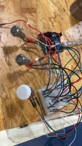
Colla-Draw – Kris – Rudi – Interaction Lab Final

CONCEPTION AND DESIGN:

It is a collaborative drawing machine aims at promoting and inspiring collaborative work, cooperation and communication. In real case it could be used as an ice-breaking game; as the cooperative task provided is designed to be both simple (in terms of abstraction: i.e. it does not require players to manage a company together, but simply drawing a picture), but also difficult (in terms of collaboration: without collaboration it is almost impossible to finish the task ) it may also be used by researchers to study how human beings interact with each other in a collaborative work. The device requires 4 players to play with. In front of the m is a large screen with a special pen on it:
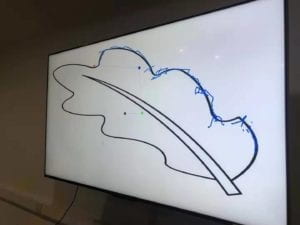

Notice the 4 colorful circles in the screen and the lines connecting them. These together are the pen. Three players will have a handy device in their hands, which contains a “spin-able” part. Players spin it to control the rotation of each circle on the pen. The last player has 2 buttons in hand, the red one is to draw (from the tip of the pen which is the red circle) and the black button it to undo the previous stroke:
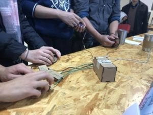
three most important designs in this project are: the rotation control unit. The handle and the style of the pen. With the development of our project the design of these three kept changing.

For the spin control unit, the ideal choice is to use a rotatory encoder. We tried it for several days, but then we realized we were facing a fatal problem. (The only time I stayed overnight since college is to solve the problem) with the help of Tristan I almost hacked the microcontroller of Arduino Uno but finally failed (It will be detailed recorded in the next part). The second alternative is quark: to use motor inversely, as we learned at class if we spin a motor it will generate electric signals. But then I realized it needs complex circuits to make the motor able to send out signals in two rotation direction. As the due time is approaching, we have to go back to potential meter. A drawback is that I can only rotate it 360 degrees then got stuck. In observing the players in ima show we find occasionally it slightly affects the performance of the device.

We paid attention to very details of user experience, and the handle is designed very smartly using human engineering. The shape of it fits very well with human hands (see the pic above) and people are happy holding it. We laser cut the boards and put them together. I suggested of using 3D printer before but steve reminded me that there are some small and delicate parts in it and 3D printer is not accurate enough.

As for the style of the pen. We pursue a simplicity in the design of the shape, yet we, again, paid attention to very details of user experience. The color of each circle corresponds to a color tape in the players device. We adjusts the radius of the circle, the size of the circle, the size of the pen stroke many times and ask people to test different versions to hasve best visual effect. The function of the pen is actually inspired by a visualization of Fourier transformation, but I’ll stop talking about math here.

FABRICATION AND PRODUCTION

#A Full Record on Rotatory Encoder#

To me it is the most exciting part. Indeed as Rudi said we should have changed our direction the minute we realized the problem, but my problem is that I could not resist new knowledge (A conflict on pin interrupt?? what’s that?? & I need to control registers in microcontroller to solve it? cool!). Although I failed, that night offers me knowledge and experience that I could hardly get in class, and I’m not regret of that.

This part is also a review for myself about what I learned in that breezeless night.

1.
The problem starts with the library that use the rotatory encoder: it asks as to make an object:

Encoder myencoder

Then call the counting function like:

encoder.counting()

yet weirdly we don’t specify pins here! After Steve tried every pins he finds only when we connect the encoder to pin2 and 3 it works. But we need to connect 3 encoders on the Arduino. Anyway this default use of pins is weird so i checked the source file in cpp.
In the source I found many unfamiliar things: some hexadecimal value assignment to a constant called PCINT, and another called some MASK, a function call “sei()” appears in the middle of nowhere, a function define “ISR()” without any return type… But I do recognize one lines: digitalRead(2) (and 3).

2.

Tristan gives a simple solution. He suggests me to copy paste the file, reset the pins in the digitalRead, then I can have to different objects in my code using different pins. But the IDE raised errors of “redefine variables”, then Tristan reminds me to change all the variables to avoid that. In doing it most of the problem got solved, with only one left: “Error: redefinition of __vector_5()__”.

3.
I scroll the codes up and down without finding and words in the text that looks like a “__vector 5__”. Finally I realized it is a situation I had no experience before, and it might has something to do with all the “sei”s and PCINTs above. Then I google.

after about 1 hour I had some basic ideas about it

#vecter 5 is a variable of Pin Interrupt that governs a range of pins including pin2 and 3.
#A PIN interrupt can be considered as a event listener, when the value on a pin changed, it will trigger the interrupt, which will stop the current calculation in processor and run a new function
# the function is ISR()
#There are three pin interrupts: vector 3 4 5: they are not defined explicitly: the variable PCINT refers to a register with 2 bits that controls the open and close of a pin interrupt; as each interrupt governs a range of pins, MASK is another register that specify a certain pins to listen to.
#sei(); means to start monitoring interrupts

4.

That’s why it specifies pin 2 and 3. Therefore if I could set the code to use a new pin interrupt, say vector 4, I could set new pins and solve the problem. Understanding all the theories in the next several hours, the last thing to do is to study the documentation of the microcontroller on Uno: basically to find which interrupt corresponds to which PCINT and MASK register digit and correspond to which pins.
In fact it worked. I changed the pins and connect it to the encoder, it gives correct output. But when I tried to put two together, there is always one of them not working. I did various experiment and found one thing: as mentioned I copy pasted the codes so I have two of them compiling together, only the encoder connected to the code that is firstly compiled works. It means there are still some hardware resource that are shared by the codes.

Then I found the code refers to another library, a look at it shows it is a timer library uses processor clock pulse, other types of interrupts (there are other types besides pin interrupts) …. Fine.

——————————————————————-

We missed user test because on it, yet we conduct our own user test later. many useful suggestions were offered and I have recorded some of them in the first section. The idea of different color circles is a feedback from the users, also based on feedback I improved the rotation algorithms to make the drawing process more smooth….

CONCLUSIONS:

It is a great success in IMA show. There are always people in front of our table. Strangers came together, had a great time in this collaborative game, and some of them even become friends and exchanged wechats. Among them, one representative from the manufacturer of Arduino is very interested in our project. Hearing our problem in the encoder, he assed steve’s wechat and told us he could help with the problem and provide us with better equipment to remake it. In general the final project does not fail us.
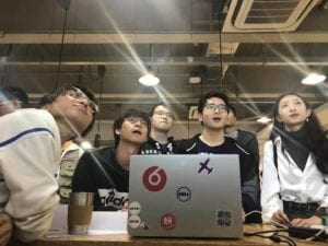
*Interestingly, as a work focusing on collaboration, it is also done collaboratively. Steve and me have been partners since midterm and we worked together extremely well. Here I would like to show my gratitude to Steve.

*At thus end of the semester, I would also like to say thanks to Rudi, for… well for everything in these two semester.
Final Project: Pirate Chase 2.0 – Audrey Samuel – Professor Rudi

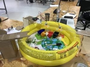
For our Final Project we decided to improve upon Pirate Chase (our midterm project) and create a new and improved version of our game! Pirate Chase 2.0 is a boat racing game which requires two or more players to blow on their boats to reach the Treasure Chest. Players are allowed to blow on the other participants boats and must avoid letting their boats sink. In the Final Project, we included a few moving obstacles to make the game even harder. We gave our game a Pirate theme because we wanted to see how competitive the participants would get when trying to capture the treasure. We got our inspiration for this from the Economic Theory of the Tragedy of the Commons and wanted to analyze how far individuals would go to push their opponents away from reaching the treasure. In thinking about how our participants would interact with our project, we decided to use a round baby pool (60cmx30cm) as our “ocean” instead of the original rectangular shaped box, as we thought it would be more interactive if individuals could move freely around the circle, without being constrained by the four corners of a box. We also incorporated Processing into our game, by setting up a countdown as well as graphics to display when players should start the game and when a player wins the game. We also downloaded the Sound and Minim library to help us play the Pirates of the Caribbean theme song.


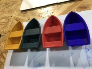
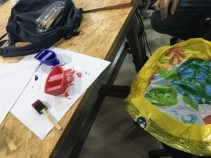
We included two obstacles, namely wave-making machines that produced waves in the water making it harder for individuals to blow on their boats directly towards the treasure. We also painted our boats blue, red, green and yellow to improve the design of our previous boats and make it more clear to users as to which boat belonged to which participant. We 3D printed wider boats as people had been complaining earlier that the boats sunk really fast. We also still used the infrared sensor to detective when the boats reached the treasure chest. We thought of using the color sensor to detect which boat won and customize the screen to show the winner but unfortunately we were not able to implement this fully.

Painted Boats

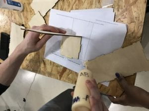
The production process involved a lot of work but we had a fun time throughout the entire process. We 3D printed four new boats and painted them in different colors. We also laser cut two boxes to support our “bridge” on which we would place our obstacles. Initially we had planned to place the treasure chest and infrared sensor on the bridge as well but we found that the pool was too small and the game would end sooner than we expected. We therefore fixed the infrared sensor and treasure chest separately on one end of the pool and the obstacles in the middle of the pool to make it harder for participants to reach the treasure. During the user-testing session, we were told that the users could not see the screen and play the game at the same time because we had placed the laptop screen on the side. We therefore had the screen lifted up and placed it right behind the treasure chest so that the participants could clearly see when the timer had gone off and when they had won the treasure. We were also told to hide the arduino and breadboard as it was pretty distracting. One thing we had to keep in mind was the obstacles falling into the water. Using water and electronics together was quite scary but we were able to pull it off in the end. At the end of the day, our ultimate aim was to see how competitive the users would get over non-existent treasure, and it worked just as we had assumed. People became more competitive when they were told there was an end goal to meet. Applying this to the Tragedy of Commons theory, individuals will be more likely to compete and drive their opponents away in an attempt to achieve limited resources, and in our case this was the treasure chest.

In conclusion, the main aim of our project was to showcase the “Tragedy of the Commons” concept (which was first introduced by American ecologist Garrett Hardin) through a fun and interactive game. Through the game we hoped to see how participants would react in a situation where there exists limited resources in a specific area, and in our case it was the treasure chest. Most importantly, we wanted our project to be as interactive as possible. Referring back to my definition of interaction, I stated that I had originally seen interaction as a form of communication, however I added to this definition stating that it is not only a form of communication, but also a way of blending technology and human abilities together in the most natural way without undervaluing the capabilities of humans, to therefore fulfill a greater aim. By allowing students to blow on the boats, I hoped to show how important human interaction was in using electronics. 

The participants who took part in the game loved the idea of blowing on the boats and said they had a lot of fun competing against their friends. If we had more time, we would get a bigger pool, so that all four boats could be used in the game instead of two. We would also include stable obstacles such as shark fins to make the game even harder. With respect to the Processing side of things, we would add  more audio/visuals to show who won, perhaps by including the sound of coins to represent treasure. We had to keep revising our project, making sure our boats floated as our first ones had not, and by merging both human interaction and computer interaction, our project in the end aimed to show these two things can work together in harmony. Bret Victor encourages us to not restrict interaction to the use of a single finger on a touch screen which is why we decided to incorporate “blowing” and physical movement in our project. This therefore allows individuals to truly feel as though they are not being undervalued, with the computer doing all the work, but rather sets an equal balance between man and machine. Ultimately, by the end of the class I have learnt what interaction truly means and how we can incorporate both human interaction and computer interaction into a project to help users learn something useful while also having fun. (Find below a video of our Project during the IMA End Of Semester Show).

LED Biking Jacket – Sagar Risal – Rudi

When first creating this jacket I wasn’t really invested in the material of the jacket, since I knew I just needed any jacket that could hold all the circuitry that it would have. I also recognized that the jacket I would need would have to be of a thinner material so that the LEDs could shine through, so I thought it would maybe be a good idea to put a bigger jacket over it, as to hide the wiring. In the end I ended up not having the bigger jacket over it, since I thought I did a good job of hiding the sewing  I did on the jacket. I also knew the user would need a way to turn on the indicators in a way that would be easy for the user to do as well as safe for when they would be biking. For this reason I decided to add gloves to the jacket so that the user had access to buttons.  I then decided that I would put the buttons on the gloves near the finger so that the user had very easy access to pressing the button and indicating in which direction they were going. I thought of maybe purchasing a real biking jacket with actual biking gloves, as to make the outfit feel more legitimate, but the overall cost steered me to instead find a cheap jacket. If I had a lot more time, and money, I would’ve loved to integrate the wires inside the actual jacket material, so they wouldn’t show.

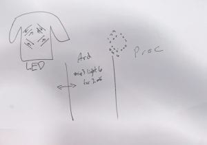
While creating the jacket there were three main humps. These were, the actual design of jacket and how I would make it and how it would look, the communication between Arduino and Processing and how it would play into the jacket, as well as how the lights would look. These three were all huge parts of the production of the jacket and how it would turn out in the end. One of the biggest struggles for me at first was how I would be able top have LEDs on the back of the jacket showing animations. At first I thought having an LED matrix on the back of the jacket would be a good idea, but after looking at the schematics of it and how much time it would take to do it, I thought that it would be better to have four LED strips and control each individual LED strip to make the desired animations. This would make it a lot easier to make the jacket itself, as well as code for the animations. This decision was a big part of how I would proceed to do my project, since the matrix idea was more Processing based, while having four LED strips would be handled majority by Arduino. I would say that I ended up coming successful in these three humps, except for the fact that I didn’t have time to code for the ability for the user to change the colors of the jacket, which I thought would be a really nice addition. 

Matrix Sketch                                      Four LED Strips Sketch

IMG_4887

In user testing I was missing majority of my project, and though most students liked the idea of LEDs on a jacket and being able to control them for the practical purpose of riding a bike, many of the teachers wanted me to add more elements to the jacket, which is where one of my proudest success came from. Ironically the success wasn’t from the jacket but instead the interface of which one could interact on Processing with the jacket.  I was really proud of the interface because of how it complemented the theme of the jacket, as well as do nice job of showing the interaction between the user and the jacket through the computer. The interface allowed me to play more with the theme that the jacket would follow, as well as how the user would be able to interact with the jacket, while still following the practical use of the jacket itself.  

When I set out to make this project I wanted to make a jacket that could be worn by bikers, so that when they bike at night they are able to be seen by cars as well as by other bikers who, especially at night, don’t know in which direction one is turning. After witnessing many biking accidents here in China, as well as being in a couple myself, I noticed that most of them happen at night    where visibility is low and riding itself is difficult because of the fact bikes have to share the road with pedestrians as well as electric scooters. I wanted an easy as well as cool way in which bikers could safely traverse the streets without feeling like they can’t be seen. I also wanted the driver to interact with the jacket itself, which is why I added buttons, as well as an interface where the user can change the animations to what they want. I have always defined interaction in levels instead of just having interaction, or not having. Obviously just pressing buttons on a jacket isn’t much of an interaction, but when thinking about the bigger picture of how one is able to choose what animations they want on their jacket as well how the usage of the jacket itself and how it lends to interacting with people on the streets while biking, it shows how just be able to control what your clothes do on your body you are able to interact with more than just two buttons on your gloves. 

During my final presentation many of my peers enjoyed the project, but also offered many recommendations that I myself wanted to include in the project but I couldn’t because of time. This included a brake light, as well as feedback for the user when pressing the buttons, so that the user could have some indication that the lights were working in the right way, since the user cannot see the lights themselves. These were all recommendations that I thought were very helpful towards how I could improve the jacket. If I had more time with this project I would’ve loved to add more customization options, as well as take the recommendations I received into my project. I would have also loved to improve on the look of the jacket itself, so that it can look and feel like a regular bike jacket but have LEDs as well. 

One thing that I definitely learned from this project is that combining technology with fashion, or just clothes in general, takes a lot of time, effort and patience. Not everything works the first time and one has many different factors when designing a meaningful way to use technology in ones clothes. The whole process is very tiresome but very rewarding when one is able to do it successfully, making the technology work meaningfully as well as look good.   Clothing and technology, while two very different things, are a lot more similar than one thinks. While humans start using technology more and more in their daily lives, it should be natural that we start adapting it to fit our clothes, which is also necessary for every day use. The more and more comfortable we get with technology and how we can implement it into what we wear, the easier daily life can become, with having simple tasks be able to be done from our clothes instead of our phone or additional technology. My LED biking jacket shows something as simple as a jacket with lights can be used to help solve issues of safety on the road, as well as offer a different style to the bikers who use it. As technology gets better and more incorporated into what we wear, one will be able to interact easier with more from their daily lives, from the simple action of just wearing their clothes. These interactions we have with what we wear, not only can look really cool, but also have a big impact with how we interact with each other in the future.

Arduino Code: 

#include <FastLED.h>
#define LED_PIN 7
#define LED_PIN_2 6
#define LED_PIN_3 5
#define LED_PIN_4 4
#define NUM_LEDS 18

#define NUM_OF_VALUES 3 /** YOU MUST CHANGE THIS ACCORDING TO YOUR PROJECT **/
/* This is the array of values storing the data from Processing. */
int values[NUM_OF_VALUES];
int valueIndex = 0;
int tempValue = 0;

CRGB leds[NUM_LEDS];
CRGB leds_2[NUM_LEDS];
CRGB leds_3[NUM_LEDS];
CRGB leds_4[NUM_LEDS];

int leftButton = 8;
int rightButton = 9;

void setup() {
Serial.begin(9600);
values[0] = 1;
values[1] = 1;
values[2] = 1;
FastLED.addLeds<WS2812, LED_PIN, GRB>(leds, NUM_LEDS);
FastLED.addLeds<WS2812, LED_PIN_2, GRB>(leds_2, NUM_LEDS);
FastLED.addLeds<WS2812, LED_PIN_3, GRB>(leds_3, NUM_LEDS);
FastLED.addLeds<WS2812, LED_PIN_4, GRB>(leds_4, NUM_LEDS);

//LEFT SIGNAL
pinMode(leftButton, INPUT_PULLUP);

//RIGHT SIGNAL
pinMode(rightButton, INPUT_PULLUP);

}

void loop() {

getSerialData();

if (digitalRead(leftButton) == LOW) {
//Play left animation
if (values[0] == 1) {
Left1();
Left1();
Left1();

}
if (values[0] == 2) {
Left2();
Left2();
Left2();

}
if (values[0] == 3) {
Left3();
Left3();
Left3();

}
}
else if (digitalRead(rightButton) == LOW) {
//Play right animation
if (values[2] == 1) {
Right1();
Right1();
Right1();

}
if (values[2] == 2) {
Right2();
Right2();
Right2();

}
if (values[2] == 3) {
Right3();
Right3();
Right3();

}
}
else {
if (values[1] == 1) {
Forward1();
}
if (values[1] == 2) {
Forward2();
}
if (values[1] == 3) {
Forward3();
}
}

}

void Direction1() {

for (int i = 18; i >= 0; i–) {
leds[i] = CRGB (255, 0, 0);
FastLED.show();
delay(40);
}

for (int i = 18; i >= 0; i–) {
leds[i] = CRGB (0, 0, 0);
FastLED.show();
delay(40);
}

}

void Direction2() {

for (int i = 0; i <= 18; i++) {
leds[i] = CRGB ( 255, 0, 0);
FastLED.show();
delay(40);
}
for (int i = 0; i <= 18; i++) {
leds[i] = CRGB ( 0, 0, 0);
FastLED.show();
delay(40);
}

}

void Blink() {

leds[0] = CRGB(255, 0, 0);
leds[1] = CRGB(255, 0, 0);
leds[2] = CRGB(255, 0, 0);
leds[3] = CRGB(255, 0, 0);
leds[4] = CRGB(255, 0, 0);
leds[5] = CRGB(255, 0, 0);
leds[6] = CRGB(255, 0, 0);
leds[7] = CRGB(255, 0, 0);
leds[8] = CRGB(255, 0, 0);
leds[9] = CRGB(255, 0, 0);
leds[10] = CRGB(255, 0, 0);
leds[11] = CRGB(255, 0, 0);
leds[12] = CRGB(255, 0, 0);
leds[13] = CRGB(255, 0, 0);
leds[14] = CRGB(255, 0, 0);
leds[15] = CRGB(255, 0, 0);
leds[16] = CRGB(255, 0, 0);
leds[17] = CRGB(255, 0, 0);

FastLED.show();
delay(500);
leds[0] = CRGB(0, 0, 0);
leds[1] = CRGB(0, 0, 0);
leds[2] = CRGB(0, 0, 0);
leds[3] = CRGB(0, 0, 0);
leds[4] = CRGB(0, 0, 0);
leds[5] = CRGB(0, 0, 0);
leds[6] = CRGB(0, 0, 0);
leds[7] = CRGB(0, 0, 0);
leds[8] = CRGB(0, 0, 0);
leds[9] = CRGB(0, 0, 0);
leds[10] = CRGB(0, 0, 0);
leds[11] = CRGB(0, 0, 0);
leds[12] = CRGB(0, 0, 0);
FastLED.show();
delay(500);
}

void getSerialData() {
while (Serial.available() > 0) {
char c = Serial.read();
//switch – case checks the value of the variable in the switch function
//in this case, the char c, then runs one of the cases that fit the value of the variable
//for more information, visit the reference page: https://www.arduino.cc/en/Reference/SwitchCase
switch (c) {
//if the char c from Processing is a number between 0 and 9
case ‘0’…’9′:
//save the value of char c to tempValue
//but simultaneously rearrange the existing values saved in tempValue
//for the digits received through char c to remain coherent
//if this does not make sense and would like to know more, send an email to me!
tempValue = tempValue * 10 + c – ‘0’;
break;
//if the char c from Processing is a comma
//indicating that the following values of char c is for the next element in the values array
case ‘,’:
values[valueIndex] = tempValue;
//reset tempValue value
tempValue = 0;
//increment valuesIndex by 1
valueIndex++;
break;
//if the char c from Processing is character ‘n’
//which signals that it is the end of data
case ‘n’:
//save the tempValue
//this will b the last element in the values array
values[valueIndex] = tempValue;
//reset tempValue and valueIndex values
//to clear out the values array for the next round of readings from Processing
tempValue = 0;
valueIndex = 0;
Flash();
Flash();
Flash();
break;
//if the char c from Processing is character ‘e’
//it is signalling for the Arduino to send Processing the elements saved in the values array
//this case is triggered and processed by the echoSerialData function in the Processing sketch
case ‘e’: // to echo
for (int i = 0; i < NUM_OF_VALUES; i++) {
Serial.print(values[i]);
if (i < NUM_OF_VALUES – 1) {
Serial.print(‘,’);
}
else {
Serial.println();
}
}
break;
}
}
}

Processing Code: 

import processing.serial.*;

int NUM_OF_VALUES = 3; /** YOU MUST CHANGE THIS ACCORDING TO YOUR PROJECT **/

Serial myPort;
String myString;

// This is the array of values you might want to send to Arduino.
int values[] = {1,1,1};
char screen = ‘H’;

void setup() {

size(1440, 900);

printArray(Serial.list());
myPort = new Serial(this, Serial.list()[ 5 ], 9600);
// check the list of the ports,
// find the port “/dev/cu.usbmodem—-” or “/dev/tty.usbmodem—-”
// and replace PORT_INDEX above with the index of the port

myPort.clear();
// Throw out the first reading,
// in case we started reading in the middle of a string from the sender.
myString = myPort.readStringUntil( 10 ); // 10 = ‘\n’ Linefeed in ASCII
myString = null;
imgLeft = loadImage(“LeftReal.jpg”);
imgMenu = loadImage(“Menu.jpg”);
imgForward = loadImage(“Forward.jpg”);
imgRight = loadImage(“Right.jpg”);
}

void mousePressed() {
if (screen == ‘H’) {
mousePressHome();
} else if (screen==’L’) {
mousePressLeft();
} else if (screen==’F’) {
mousePressForward();
} else if (screen==’R’) {
mousePressRight();
}

//sendSerialData();
}

void sendSerialData() {
String data = “”;
for (int i=0; i<values.length; i++) {
data += values[i];
//if i is less than the index number of the last element in the values array
if (i < values.length-1) {
data += “,”; // add splitter character “,” between each values element
}
//if it is the last element in the values array
else {
data += “n”; // add the end of data character “n”
}
}
//write to Arduino
myPort.write(data);
}

void echoSerialData(int frequency) {
//write character ‘e’ at the given frequency
//to request Arduino to send back the values array
if (frameCount % frequency == 0) myPort.write(‘e’);

String incomingBytes = “”;
while (myPort.available() > 0) {
//add on all the characters received from the Arduino to the incomingBytes string
incomingBytes += char(myPort.read());
}
//print what Arduino sent back to Processing
print( incomingBytes );
}

void draw()//Title Screen
{
if (screen == ‘H’) {
drawHome();
} else if (screen == ‘L’) {
drawLeft();
} else if (screen == ‘F’) {
drawForward();
} else if (screen == ‘R’) {
drawRight();

}

// echoSerialData(20);
}

void keyPressed() {
printArray(values);
sendSerialData();
}

Recitation 10 Documentation – Jackson Simon

For this recitation, the workshop recitation, I decided to attend the one on Serial Communication by Mister Young. I feel it was quite important for my project, since I would need to both be communicating from Arduino to Processing and Processing to Arduino at the same time.

I learned how to make a sensor value from the Arduino influence Processing (for example, in my Final Project, an accelerometer influenced whether the game would continue in Processing).

In this simple example shown in the video below, I connect an Infrared Sensor to Arduino and map the values from 0-1023 to 0-50 and have them being read in Processing.

It ended up being useful (at the start of my project, before I decided to have the start of the game be a different way than with an infrared sensor) since when a person would walk in front of the sensor it would turn on the game in Processing, and start the audio from Processing.

Final Project:Truth about Truth – Chloe(Yuqing) Wang – Rudi 

Truth about Truth – Chloe(Yuqing) Wang – Rudi 

My idea of how this installation would look like changed a lot during my development process. At first I wanted to be a complicated series of questions and answers with data collected from user interactions. But after talking to various people about my project, I gathered different opinions and came up with the final version. 

Artist Statement

Contemporary media has the power to shape the way we think. We are all blind when it comes to truth. In this environment, how do we determine right from wrong, black from white? In what ways do we interpret something as a fact and how likely is it for us to view something/someone without prejudice?Truth about Truth is an installation that is intended to remind individual observers the importance of not categorize and define others from only one perspective, not to have our decisions influenced by what the media portrayals or merely considering what’s on the surface. However, this work is also open to all interpretations. 

Conception and Design

As written in my final essay, I based my project on two medi theories: “Selective Exposure” and “Third-Person Effect”. Selective Exposure means that people have the tendency to read and accept those news that are in accordance with their beliefs. Third person effect is the concept that individuals believe others are easily influenced by the media but they themselves are not. With this project, I wished users can slowly explore by themselves and come to their own understanding of what this project is about. 

The Three photos

Changing the images to any group photo would make sense, but in this case, I choose three images with opposing groups of people in them. If we look at these images without cropping out the individual faces, we can automatically give each of them a definition, a job title, and we decide whether they are good or bad people. 

1.Hong Kong Protest: I got the idea of my project because of the Hong Kong protests. For me, the protest did not happen only on the news, but they have impacted some of my closest friends who were studying in Hong Kong. As someone sandwiched in between the two sides of this conflict, I wish to maintain a neutral perspective. Each person holds their own perspective when looking at this image. By cropping out the individual faces, I wish to put the emphasize individuals’ roles in this whole situation. Interestingly, although the image I use doesn’t explicitly say that it is Hong Kong, many people automatically relate the image to the Hong Kong protests. This shows that a pre-set image of what the protesters and the polices are like. 

Image1 (combined two photos)

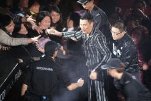
2.Andy Lau: I think this image can successfully reflect my main idea of media portrayals and the star-making process. Andy Lau is one of the most well-known and commercially successful Chinese singers. His fame was built by mass media in China in the 1990s. Being the focus of this image, Andy Lay is still a well-known figure even when cropped out. The media has made us(at least the Chinese users) connect Andy Lau’s face with fame. People get crazy when they see him. So in this image, Andy Lau is separated from everyone else. He is a commercial phenomenon, while the others are consumers of this fame.

image2

3.Occupy Wall Street in 2011:There are not so many protester-police opposition images that are available. I chose an image of the 2011 Occupy Wall Street protest. This protest was about economic inequalities in the U.S. Many were arrested while the police and protestors conflicts were intense. With this image, it does not limit the topic of this project to just China. Who’s side are you on when the protest is happening in New York? How are people’s perspectives changed when the context of the image is not so obvious and recent?

image3

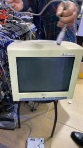
The Vintage MonitorFor this project, I didn’t want to have my project shown directly on my computer screen. My initial idea was to laser-cut a box that can cover my computer so it would look like a TV screen. Then I wanted to have an old TV set that is smaller, with buttons on the sides, to create a more intuitive user experience. I have also considered getting a newer monitor, but it still does not fit the aesthetics and goals I want to achieve with this project. However, what I found in the second hand market was a huge monitor with a rather high resolution. With the monitor, I wanted to make the users feel as if they are controlling a surveillance camera to observe individuals, as the set-up of this machine only allows you to look at one face at a time unless you press the button. There is another layer of meanings. Nowadays with our smartphones and laptops, we feel like er control the world, we know everything that is happening, we can easily reach out to those we want to talk to or comment on things we want to comment on. However, at the time when this monitor was used, information is only starting to be transferred faster. At the same time, with this machine, it also shows that the social media today only gives us fragments of information. You still cannot fully understand someone just by looking at  a small fragment of their face.

love at the first sight

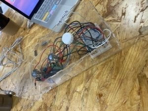
The Case: The clear case for the Arduino is also a hint to the title of my project. I remember in class we talked about putting an input to a black box and receiving an output, but we don’t know what happens in between. This transparent case is to show that there are lots going on underneath the deceptive surface. I think it was necessary in this project, to have a see-through wire case.

The Transparent Case

Sound Effects: The sound effects as the user is turning the knob signifies surveillance camera focused on individual faces. Although this interpretation might be adding another layer to the project, it has made the project more engaging for the users. Although I received recommendations to add some background music to my project, I realize that if the project was in an environment like the IMA show, adding a background noise would not improve the whole experience. 

Fabrication and Production

I started my project based on what I have done in one of the recitations where users can control two potentiometers to reveal parts of an image. At first, I wanted to make a similar interaction device with other sensors. But I realized that my ideas can be better expressed if it only reveals faces. So I chose the first police and protestors image and cropped out those people’s faces with Gravit, labeled them image1 to image13. The last image is the original photo. I also used two push buttons and one potentiometer for the actions of revealing the whole image, changing the image, and changing individual faces. One problem I encountered was that the images all had different sizes. Rather than changing the canvas size every time, I fitted all the images to the same size so the image change was smoother. 

Cropped out faces
Cropped out faces

User Testing

The user testing process helped me to foresee many problems that could occur once the project is done. Many people also gave me critical suggestions for my project. During user testing, I only had one image and two buttons. They wanted more images and more ways to interact with the machine. I also realized that people tend to push the buttons first and only focus on the screen. The light-up button did not signify “press me” for the users. Everyone interpreted the project as: focusing on individuals as parts of a whole. Some people thought that one image was enough to explore and it gives a strong statement. While others wishes to see more images so the project has a more diverse or complete storyline. Furthermore, most liked to have the image only revealed when the knob was turned to the end. Because of this suggestion, I changed this part for the final version. However, I did not realize adding more images is already making the installation more complicated. I should have the image revealed more often as the user is turning the knob. 

Video: User-testing version

To organize the wires but still showing them for the aesthetics, I laser-cutted a clear box that can fit the breadboard, Arduino, and can fit in front of the monitor while not blocking the screen. I also made sure to have three holes with the size of the two buttons and the potentiometer. Then I 3D printed a knob for the potentiometer. However, when I assembled the case to the buttons, the potentiometer was not so stable. So I soldered it and put a tape underneath to support the potentiometer. 

Here are some photos of the building process:

Building Process

In one of the images, there are 13 faces. While the other two have 7 faces. To make sure the potentiometer can evenly spread out the degree it turns to the number of images, I used the map function in Processing.   

  prevknobValueMapped= int(map(sensorValues[0], 0, 1023, 13, 1 ));
  prevknobValueMapped2= int(map(sensorValues[0], 0, 1023, 6, 1 ));
  prevknobValueMapped3= int(map(sensorValues[0], 0, 1023, 5, 1 ));

Because there are three different images each with different faces cropped out, I had to separate them as three groups of images with three individual folders: pic1, pic2, pic3 in the data folder. To retrieve those images from those folders, I used

  for (int i=0; i<14; i++) {
    photos[i]=loadImage("pic1/image"+i+".jpg");
  }

and

    if ((sensorValues[1] == 1) &&(knobValueMapped == 13) ) { //sv1 = big picture, sv0=knob
      image(loadImage("pic1/image14.jpg"), 0, 0);
    }

The two push buttons correspond to two digital values and the potentiometer corresponds to the analog value. They only have 1 and 0 two values of whether they are being pressed or not. 

This is the code for the second group of images:

    if ((sensorValues[1] == 1 ) && (knobValueMapped == 6)) {
      image(loadImage("pic2/image7.jpg"), 0, 0);
    }
    if (prevknobValueMapped2 != knobValueMapped) {
      sound.play();
    }

Conclusion
I wanted to show that contemporaty media has the power to shape the way we think, and that individuals matter. During my mid-term project, I defined games as the most interactive forms of art. However, they are only interactive because they are immersive.  The process of developing my ideas for this project and finally getting it done has been quite a journey for me. There were many times when I got lost in my own ideas. However, the end result of my project was successful for me. All the users I interviewed came to the conclusion that individuals are more important in the big picture. Most people I saw were able to figure out how this installation was operated if they focused on it for longer periods of time. However, I still needed to improve the intuitiveness of the machine. Many people got lost when using it, and even if I put a note explaining how to use it, people still would not read it. Although the machine’s “complication” can make people want to explore it more, some people do not have enough patience to explore, or they simply did not see the button lighting up and did not interprete it as time to press them. If I had more time, I would add more images and try to make the operation of my project simpler. From this project, I realized that everyone thinks differently. It is quite difficult to arrange three input values that fits everyone’s habits. I used some  images that can be considered controversial in this project, but there were no words accompanying the images so there is not a forced understanding to my project. Also, because I used three “irrevalent” images, this project covers quite a diverse topic and can be applied to more areas, which traces back to my initial struggle of being neutral and not taking sides. 

Here are all the version of my codes for the final project: https://gist.github.com/Chloeolhc/2662115e00a0ab9844e73ec224b66792

Here is a video of the final presentation of my project:

Sources:

https://www.mpweekly.com/entertainment/focus/local/20170120-33977

https://www.thepeninsulaqatar.com/article/02/09/2019/Hong-Kong-students-rally-peacefully-after-weekend-of-protest-violence

https://www.flickr.com/photos/akinloch/6207968006

https://www.channelnewsasia.com/news/asia/hong-kong-protests-police-children-bullied-data-leak-yuen-long-11746034