Recitation 9: Media Controller by Isabel Brack

Overview

For this recitation I used an image of my dog and ovelayed two different tinted images at different X coordinates to create a paneled image. The opacity of the tints is controlled by a potentiometer, which I mapped to the tint. I also tried to map a blurring effect using a second potentiometer which worked but created a lot of lags and glitches so I ended up commenting it out for the final documentation of the recitation. The first try at mapping the potentiometer I only included one image tint and the mapping was a bit jumpy because there was a loose connection between the potentiometer and the breadboard.

Reading Connection

In contrast to the examples of computer vision from Computer Vision for Artist and Designers that spanned abstract, funny, and sociopolitical themes, my use of computer vision is quite basic comparatively only manipulating the opacity and tint of three different panels in a processing image of my dog. The technology I used did not capture a live image like many of the expamples like Suicide Box  or Cheese  that were both able to reckognize and record certain movements and actions like veriticle falling or smiling. Instead my project combined the physical interaction of turning a potentiometer to control the value and opacity of the different panels tint on my image. First technology was used in the physical circuit wiring, and it was also used in the display of the image and the connection between the potentiometer and the opacity of each color. I did not use any detection elements like tracking movement as I was not using live capture, but instead applied these concepts to a still image, manipulating the opacity and at some points blurring it too (but the blur created to much glitching and lagging in the program to have smooth transitions). Although I did not include a full body participation in the interaction by using a potentiometer, by reading Levin’s writing, I can appreciate the incorporation of full body participation in computer vision and in the interaction expanding the concept of interaction and making the interaction more engaging for the audience.
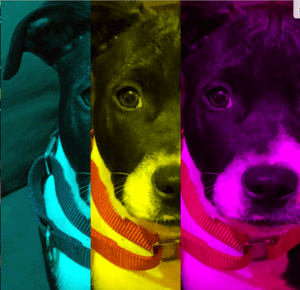
dog full opacity tint

The image at greatest opacity for color tints. (The picture is my dog, so there is no image citation.)

Working potentiometer mapped to the tint of a dog image.

IMG_5187

First try at mapping the potentiometer to the tint of an image.

Code

Processing:

import processing.serial.*;

String myString = null;
Serial myPort;


int NUM_OF_VALUES = 1;   /** YOU MUST CHANGE THIS ACCORDING TO YOUR PROJECT **/
int[] sensorValues;      /** this array stores values from Arduino **/
  
PImage photo;
PImage photo2;
 float tint;
 // float blur;


void setup() {
size(1000, 1000);
  background(255);

  setupSerial();
photo = loadImage("dog.jpeg");
 photo2 = loadImage("dog2.jpeg");
}


void draw() {
     float tint =map(sensorValues[0],0,1023,0,255);
     //float blur =map(sensorValues[0],0,1023,0,10);

  updateSerial();
  
  printArray(sensorValues);

tint(0, 255, 255, 20); 
image(photo, 0, 0);
//filter(BLUR);
//filter(BLUR, 0);
tint(255, 255, 0, tint); 
image(photo2, 300, 0);
tint(255, 0, 255, tint); 
image(photo2, 600, 0);
//filter(BLUR);
//filter(BLUR, blur);


  // use the values like this!
  // sensorValues[0] 

  // add your code

  //
}


void setupSerial() {
  printArray(Serial.list());
  myPort = new Serial(this, Serial.list()[ 1 ], 9600);
  // WARNING!
  // You will definitely get an error here.
  // Change the PORT_INDEX to 0 and try running it again.
  // And then, check the list of the ports,
  // find the port "/dev/cu.usbmodem----" or "/dev/tty.usbmodem----" 
  // and replace PORT_INDEX above with the index number of the port.

  myPort.clear();
  // Throw out the first reading,
  // in case we started reading in the middle of a string from the sender.
  myString = myPort.readStringUntil( 10 );  // 10 = '\n'  Linefeed in ASCII
  myString = null;

  sensorValues = new int[NUM_OF_VALUES];
  
}


void updateSerial() {
  while (myPort.available() > 0) {
    myString = myPort.readStringUntil( 10 ); // 10 = '\n'  Linefeed in ASCII
    if (myString != null) {
      String[] serialInArray = split(trim(myString), ",");
      if (serialInArray.length == NUM_OF_VALUES) {
        for (int i=0; i<serialInArray.length; i++) {
          sensorValues[i] = int(serialInArray[i]);
        }
      }
    }
  }
}

Arduino:

void setup() {
Serial.begin(9600);
}

void loop() {
int sensor1 = analogRead(A0);
//int sensor2 = analogRead(A1);
//int sensor3 = analogRead(A2);
//int theMappedValue = map(sensor1, 0, 1023, 0, 255);
//int theMappedValue2 = map(sensor2, 0, 1023, 0, 255);
// keep this format
Serial.print(sensor1);
//Serial.print(“,”); // put comma between sensor values
//Serial.print(sensor2);
// Serial.print(“,”);
// Serial.print(sensor3);
Serial.println(); // add linefeed after sending the last sensor value

// too fast communication might cause some latency in Processing
// this delay resolves the issue.
delay(100);
}
Recitation 9: Media Controller – Zhao Yang

Code:

https://github.com/JooooosephY/Recitation-9

Introduction:

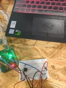
For this recitation class, we were required to use Arduino to send values to Processing to interact with some media, such as images or videos. I was interested in making some instant interaction so I chose the live camera as the media that I would change. Basically, it’s like an exercise that I used the Arduino to change the filter of the camera. Here is the video about how I interacted with the camera and an image of the circuits. 

Reflection:

I first looked up the filter function to check what kind of filter I can use. Then I found the filter POSTERIZE. Since it requires a  parameter to change the filter, I decided to use the potentiometer to change the value. I thought that if I only use the potentiometer as the tool to interact, it would be too boring. Thus, I added another button to control whether to use the INVERT filter. Fortunately, the output was pretty interesting. However, when I finished the exercise, I felt the way of interaction is still too simple. According to Golan Levin’s article, he notes that “Myron Krueger’s legendary Videoplace, developed between 1969 and 1975, was motivated by his deeply felt belief that the entire human body ought to have a role in our interactions with computers” (Levin 1). It is the first interactive artwork to incorporate computer vision. I really appreciate the Krueger’s idea that the entire human body ought to have a role in our interactions with computers. Since using buttons or potentiometer to interact are just the interaction with your fingers, the use of sensors could be a better way to create an interactive project. In my opinion, the values that the sensors can send are actually from the real world, while the values that some buttons send are the values inside the computer. So you can interact with sensors through your body. And some projects that use sensors as the input are usually more interesting than the projects that only use buttons as the input. Therefore, when I make the final project, I will try to make it a project that can involve the user’s whole body to interact with so that the project can be a good entertaining project. 

Recitation 9: Media Controller–Lifan Yu

Recitation 9: Media Controller

Lifan Yu (ly1164)

       In this recitation I changed the parameters of an image I painted, using Arduino and processing.

  1. I used the function “tint()” to change the colors. I used potentiometers to do this through serial communication.
  2. Also, when a button is pressed, my image starts moving and bounces when it touches edges.
  3. I used another potentiometer to control the blurring of this image using filter(BLUR, b);
  4. I used one more potentiometer to control zooming by adding the array of potentiometer data into my image’s size parameters:  float n=map(sensorValues[1],0,1023,0,500);  image(img1, x, y, n, n);

Zoom in and zoom out:

Tint:

Before applying these data, I mapped the original data from Arduino to suitable ranges for each parameter.

Code for Arduino:

// IMA NYU Shanghai
// Interaction Lab
// For sending multiple values from Arduino to Processing

void setup() {
Serial.begin(9600);

}

void loop() {
int sensor1 = analogRead(A0);
int sensor2 = analogRead(A1);
int sensor3 = digitalRead(6);
int sensor4 = analogRead(A3);

// keep this format
Serial.print(sensor1);
Serial.print(“,”); // put comma between sensor values
Serial.print(sensor2);
Serial.print(“,”);
Serial.print(sensor3);
Serial.print(“,”);
Serial.print(sensor4);
Serial.println(); // add linefeed after sending the last sensor value

// too fast communication might cause some latency in Processing
// this delay resolves the issue.
delay(100);
}
Code for Processing:

// IMA NYU Shanghai
// Interaction Lab
// For receiving multiple values from Arduino to Processing

/*
 * Based on the readStringUntil() example by Tom Igoe
 * https://processing.org/reference/libraries/serial/Serial_readStringUntil_.html
 */

import processing.serial.*;

String myString = null;
Serial myPort;


int NUM_OF_VALUES = 4;   /** YOU MUST CHANGE THIS ACCORDING TO YOUR PROJECT **/
int[] sensorValues;      /** this array stores values from Arduino **/
PImage img1;
float m=0;
float n=0;
float x=0;
float y=0;
float speedX=10;
float speedY=10;


void setup() {
  size(1000, 1000);
  background(0);
  setupSerial();
  img1 = loadImage("Witch.png");
}


void draw() {
  updateSerial();
  printArray(sensorValues);

  // use the values like this!
  // sensorValues[0] 
  imageMode(CENTER);
float m=map(sensorValues[0],0,1023,0,500);
  float n=map(sensorValues[1],0,1023,0,500);
  float b =map(sensorValues[3],0,1024,0,10);
    
  // add your code
  background(0);
  tint(m,m,m,m);
  
image(img1, x, y, n, n);
filter(BLUR, b);

if (sensorValues[2]==0 ){
  x=300;
  y=300;
}else{
x=x+1.7*speedX;
y=y+speedY;
if(x>width||x<0){
  speedX=-speedX;
}
if(y>height||y<0){
  speedY=-speedY;
}
}

  //
}


void setupSerial() {
  printArray(Serial.list());
  myPort = new Serial(this, Serial.list()[ 0], 9600);
  // WARNING!
  // You will definitely get an error here.
  // Change the PORT_INDEX to 0 and try running it again.
  // And then, check the list of the ports,
  // find the port "/dev/cu.usbmodem----" or "/dev/tty.usbmodem----" 
  // and replace PORT_INDEX above with the index number of the port.

  myPort.clear();
  // Throw out the first reading,
  // in case we started reading in the middle of a string from the sender.
  myString = myPort.readStringUntil( 10 );  // 10 = '\n'  Linefeed in ASCII
  myString = null;

  sensorValues = new int[NUM_OF_VALUES];
}


void updateSerial() {
  while (myPort.available() > 0) {
    myString = myPort.readStringUntil( 10 ); // 10 = '\n'  Linefeed in ASCII
    if (myString != null) {
      String[] serialInArray = split(trim(myString), ",");
      if (serialInArray.length == NUM_OF_VALUES) {
        for (int i=0; i<serialInArray.length; i++) {
          sensorValues[i] = int(serialInArray[i]);
        }
      }
    }
  }
}

       The way that technology is used in my project is the serial communication that allows users to change parameters of a picture without actually typing in those data in a computer. Rather, this process is done by interacting with physical devices, changing their input values–indirectly but simply and conveniently changing parameters into whatever values we like. This only requires an extra step of mapping values into new ranges (that fit their parameters) after we have built up a serial communication between Arduino and Processing. Using this technology, even people who don’t know much about computer programming can easily interact with that image and change it’s features.


Recitation 8: Serial Communication by Tya Wang (rw2399)

Exercise 1: Make a Processing Etch A Sketch

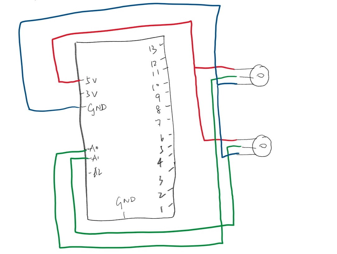
Here is a schematic of a circuit made up of two potentiometers, each controlling the x-value and y-value on the screen.

With the ellipse changing position, the program operates this way:

When you think about how Etch a Sketch works, essentially it is only detecting values on the two handles and drawing a straight line between the values returned in two continuous detects. In the video given, the reason why the lines are so smooth and real is because the toy makes detections way faster than Processing, and handles on the toy is also larger than Arduino processing, making controlling them easier. 

I think while this is a very simple and flat interactive relationship, their is quite a huge potential in what people can achieve through it. It can also help its children or even adult users to develop creative thinking by brainstorming what one single line can make up. However, I don’t think this is the best way to create art for a commoner on a daily basis because it requires some sort of artistic threshold to make a vivid picture with such limited material. Other digital drawboards with way more features would help daily art creation better.

Exercise 2: Make a musical instrument with Arduino

Building the circuit and coding is easier compared with designing how this program should be like. Since you can choose either or both of your keyboard and mouse to control the sound, which one you wants to use controlling length and tone of the notes is a central question that I needed to design to make using this program easier. Finally, I decided that while moving the mouse creating a sound might be fun, it is not quite practical. Therefore, I chose to build this classic keyboard where each key on the second of your keyboard leads to the sound of a different note. And I made the length of one sound linger a bit longer after the user stopped pressing the key to create an experience like playing a piano.

Recitation 9: Media Controller by Yiwen Hu

In this recitation I applied what we’ve learned in class, the “tint” function which can change the background color of the video. I decided to use the potentiometer to change one value of the RGB.

Step 1: Insert the video. 

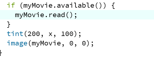
As we’ve learned in class, in setup() I wrote myMovie function and access it to the video file. I put the video file in the same folder as the processing’s, but under another folder called “data.” Then in void draw(), I wrote like this:

The tint appears after the myMovie read() if statement. And the image function is to make it appear in the sketch. As for the x, it’s the variable I created to change the color. The x will vary based on the potentiometer value.

Step 2: Let Arduino communicate with Processing 

For this step I refer to the example code in previous class. There’s not many change to it except the number of value and port number. For the processing, I put a setupSerial() in void setup() and updateSerial() in void draw(), which are defined in the following code. Another thing I create is the map function that translate the value of the potentiometer to the x, whose range should be under 255. 

After building the circuits, I run the code and it worked!