Recitation 1–Ketong Chen

First week recitation

In the first week recitation, I  successfully built 3 circuits with my partners and also learn how to solder.Here are the details.

Materials

  • 1 * Breadboard
  • 1 * LM7805 Voltage Regulator
  • 1 * Buzzer
  • 1 * Push-Button Switch
  • 1 * Arcade Button
  • 1 * 220 ohm Resistor
  • 1 * 10K ohm Resistor
  • 1 * 10K ohm Variable Resistor (Potentiometer)
  • 1 * LED
  • 1 * 100 nF (0.1uF) Capacitor
  • 1 * 12 volt power supply
  • 1 * Barrel Jack
  • 1 * Multimeter
  • Several Jumper Cables (Hook-up Wires)

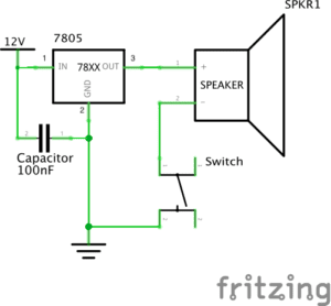
Diagam 1

doorbell

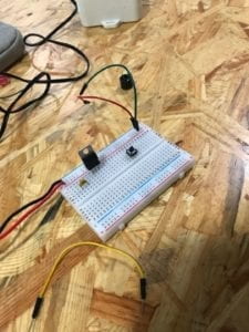
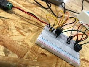
This is the first circuit we built. Though it is a simple one and we easily understand the diagram as well as finding all components, we met difficulties due to the misunderstanding of the breadboard. Later with the help of the assistance we realized how the current flows in the board(actually crosswise)and how to use wires to connect each component together. After several times adjustments, the buzzer worked! 

That was really a big motivation for us to continue the next two circuits.

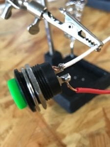
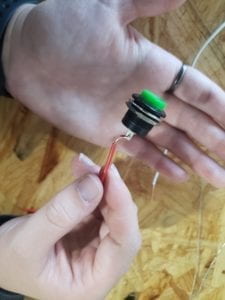
Before that, we learn how to solder long wires to an arcade button. I found it interesting seeing the professor using holes on scissors to peel the rubber off the wire, observing the silver melt and solidified. We are a little bit nervous because we need discreetly moved the small device to avoid injures caused by the high temperature (700 degree centigrade).
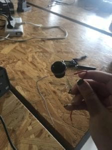
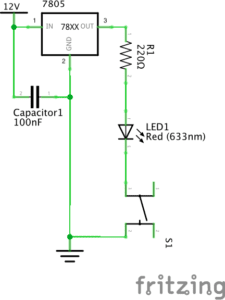
Diagram 2&3

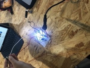
lamp

dimmable light

The circuits 2&3 are lamp and dimmabe lamp. We first used the multimeter to figure out the resistance value of the two resistance then built the second circuit smoothly. But then I come across a problem with variable resistance for I didn’t know how it woks. Later in the class I asked the Professor and understood it was like the rotary button used to adjust volume.

This is the first time I built real circuits instead of just drawing diagrams on paper(which we always did in high school Physics class)so I was excited and inspired and more willing to create my own work.

Answers to Questions

Q1: I think during the process of making the circuit the interaction exists when we connect each components together according to the diagram. We have expectations for the buzzer rings, the LED goes lighter and dimmer and all we do is to meet the goals. We connect wires in certain order and it gives us the feedbacks.

Q2: The “EyeWriter” created by Zach Lieberman inspires me that there must be a creative way to link physical movements to technology. The paralyzed painter is able to express himself using his eyes is an example. Interactive art can fully use the potential the design can reach and involve physical computing to build connections between single person and the rest of the world.
Week 1: Electronics and Soldering Christina Bowllan

Soldering

During the first recitation, we learned how to solder the wires and use this to create a simple circuit.

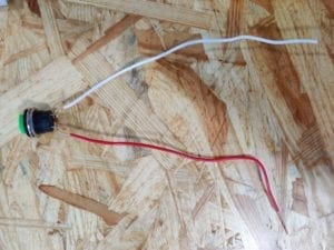
The first step in the process for my partner and I was soldering the wires in order to connect the doorbell to the simple circuit. We heated up the soldering device to about 300 degrees and then placed the wire on the heating device in order to create the solder. The way I understood it is the solder acts as a “glue” or activation site between the bell and simple circuit.

Circuits

The next step in the process was to build the circuit and we were able to successfully build diagram 1 and 2, and did not have time to start diagram 3.  In the following are the materials we used, the diagrams, and an explanation of each:

Materials

  • 1 * Breadboard
  • 1 * LM7805 Voltage Regulator
  • 1 * Buzzer
  • 1 * Push-Button Switch
  • 1 * Arcade Button
  • 1 * 220 ohm Resistor
  • 1 * 10K ohm Resistor
  • 1 * 10K ohm Variable Resistor (Potentiometer)
  • 1 * LED
  • 1 * 100 nF (0.1uF) Capacitor
  • 1 * 12 volt power supply
  • 1 * Barrel Jack
  • 1 * Multimeter
  • Several Jumper Cables (Hook-up Wires) 

Circuit 1: Doorbell 

The first time my partner and I created the Doorbell circuit, we faced a few challenges. We understood that all circuits need to be grounded and all of the various wires and resistors should be connected somehow, but we did not realize that all of the materials needed to be connected on the same half of the breadboard in order to work. In addition, we understood that wire 3 should be connected to the speaker and wire 2 should be grounded, but we did not understand where to put wire 1. In our second attempt, we placed it to the power, and these changes made the circuit work. 

Circuit 2: Lamp

Our second circuit went much better than the first one because we knew to put all the materials on the same side of the breadboard. However, one of our issues at first was understanding which resistor contained 220 ohms. We ended up researching what different resistors looked like and found the correct one to use. 

Question 1:

Interactivity in The Art of Interactive Design is defined in terms of a conversation: “a cyclic process in which two actors alternately listen, think, and speak.” The circuits we built today are interactive simply because all of the materials needed to work with one another. For example, the voltage regulator was connected to ground and so was the resistor, and in total, these all need to work with the electricity for the LED light to turn on.

Question 2:

Interaction design is essentially our creativity: this is the space where we create a product and think about how a person will use it. Physical Computing is used with interaction design in order to bring the project to life. Without physical computing, people themselves would have to “act out” or play the roles of each part of a circuit.

Connor Schone – Week 1

For our first week’s lab in Interaction Lab, my partner and I first learned how to sodder two conductive materials together by melting the end of a light metal wire to produce a sort of adhesive. Below is a photo of the resulting bond. The red and white wires were each glued to corresponding prongs on the bottom of the doorbell button to stabilize their connection.  


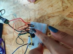
In the second section of the lab, my partner and I were tasked with making a circuit. The intended end result being a functioning doorbell that would produce a sound after a button was pressed. We began by accounting for all the components pictured in the diagram provided, and attempted to build a circuit, connecting wires from the battery at one end of the breadboard, and through the different components necessary to move the appropriate amount of electricity past the binary button and into the speaker.    

We were unable to achieve the intended result in our attempts to do so, likely due to one or more incomplete connections within the breadboard itself.