First week recitation-Xinran Fan

First week recitation

In the first week recitation, I  and my partner built 3 circuits and soldered out a button with the help of teaching assistant. The details are  as follows.

Materials

  • 1 * Breadboard
  • 1 * LM7805 Voltage Regulator
  • 1 * Buzzer
  • 1 * Push-Button Switch
  • 1 * Arcade Button
  • 1 * 220 ohm Resistor
  • 1 * 10K ohm Resistor
  • 1 * 10K ohm Variable Resistor (Potentiometer)
  • 1 * LED
  • 1 * 100 nF (0.1uF) Capacitor
  • 1 * 12 volt power supply
  • 1 * Barrel Jack
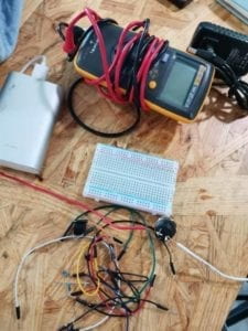
  • 1 * Multimeter
  • Several Jumper Cables (Hook-up Wires)

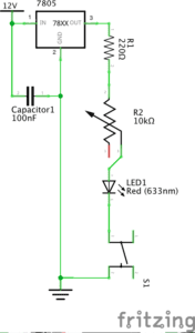
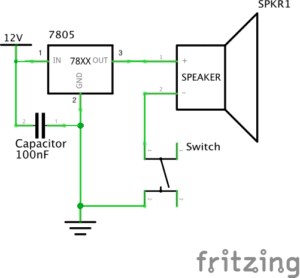
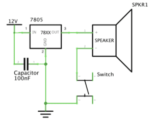
Diagam 1

doorbell

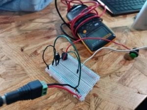
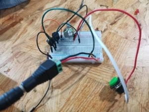
At the first we made a careful study of the diagram as well as found all components, we met difficulties for  misunderstanding  the breadboard. Thanks to the help of the assistance we finally understand the invisible connection in the board. We also put effort into learning how to  use wires to connect each component  . After several attempts, the buzzer did work! 

Video Playe

Soldering

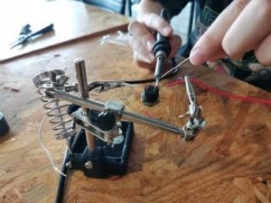
This little success really  inspired us to head forward to the next two circuits and soldering.To begin with, I used the holes on the scissors to peel the rubber off the wires, while my partner heat up the soldering iron. We really met a problem when there is no clear button left, lucky, a patient teacher helped us to clear the tin left in the hole on the iron bar. Then we carefully putting the a wire through the hole, heating the tin bar, soldering it by melting tin, and the other side.

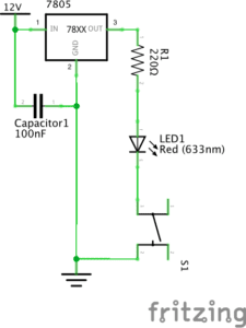
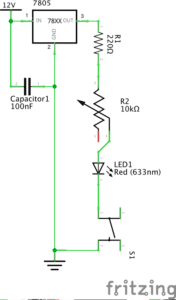
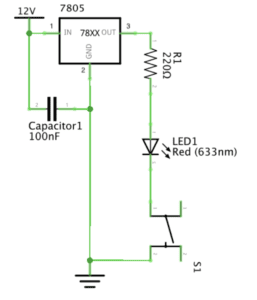
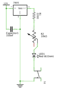
Diagram 2&3

lamp

dimmable light

The circuits 2&3 are lamp and dimmabe lamp. firstly, We used the multimeter to figure out the resistance value of the two resistance. The second circuit is quite successful, and we did not remove all the components for teachers’ suggestion. However, at the third circuit, we get stuck at the Variable Resistor , it really took us several time to work it out.

Video Player

Answers to Questions

Q1:Interactive is the conversation between two actor, in today’s recitation, this two actor are the circuit and us. For the circuit, the changes on the components are the input, or “listen”. The electric current passes through the wires. that might be the process, or “think” . The reactions of the effectors are output, or “speak” For us, we observed the reaction of the effectors , think about the proper time to operate the control system. we finally made our decision and operate it, we “speak” .

Q2:Interactive design is using devise to realize our ideas. Physical computing is processing in deed. Interactive art would not come to reality if we could not make a  Interactive design makes possible the communications between people and interactive devices. 

CATEGORIES

Documentation1:Soldering and Building Circuits

Introduction:

 In this recitation, we did soldering and built our own circuits according to circuit diagrams. My goals were: learn to solder skillfully and better my skills in reading circuit diagrams.

Materials(from the recitation instructions):

  • 1 * Breadboard
  • 1 * LM7805 Voltage Regulator
  • 1 * Buzzer
  • 1 * Push-Button Switch
  • 1 * Arcade Button
  • 1 * 220 ohm Resistor
  • 1 * 10K ohm Resistor
  • 1 * 10K ohm Variable Resistor (Potentiometer)
  • 1 * LED
  • 1 * 100 nF (0.1uF) Capacitor
  • 1 * 12 volt power supply
  • 1 * Barrel Jack
  • 1 * Multimeter
  • Several Jumper Cables (Hook-up Wires)

Soldering

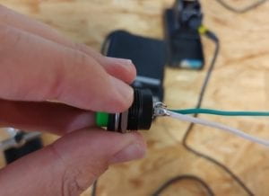
Melted tin can “glue” the wires and the switch together after it  dries.

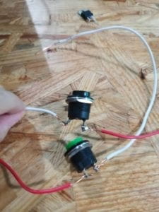
My partner and I used a soldering iron and a piece of soldering tin to connect two wires to a push-button switch. We first pealed the insulating layer on either ends of the two wires so the metal inside would be exposed. We then hooked one end of each wire onto the two iron bars on the back of the switch.

Following the instructor’s advice, we first used the soldering iron to heat up the connecting parts of the wires and the switch. Then we attached the soldering tin to those parts. The tin melted a little, but not quite in the way we hoped. (Maybe we used the tip of the soldering iron so the connecting part wasn’t thoroughly heated.) To accelerate its melting, we attached the soldering iron to the soldering tin.

We put the soldering iron there for such a long time that the plastic material of the switch melted! We took a new switch and tried again. This time we successfully connected the wires and the switch.

(The switch on top is the melted one)

Building our Circuits

Circuit 1: Door Bell

It was my first time to use a breadboard to build a circuit. It took me a while to actually understand how the holes on the breadboard were connected. Thanks to my partner’s patient explanation I finally understood how to imagine the “invisible” connections between different spots on a breadboard.

Tracing the lines on the circuit diagram, we quickly built a circuit. However it didn’t work because we were confused about how the wires can be connected to the “ground”. Our circuit didn’t work properly because it wasn’t a complete loop. Then we found out that the blue lines with a “-” symbol indicate where the wires connected to the “ground” should be put.

Circuit 2: Lamp

When we moved the wires, our circuit was short circuited. With the help of an instructor, we checked our circuit following the direction of the electrical current. Finally, the lamp lit up.


Circuit 3: Dimmable Lamp

We had become more experienced when building the third circuit. We built it with no difficulties.

Although the dimming wasn’t very obvious, it was actually dimmable. (We assume that maybe the maximum resistance of the variable resistor wasn’t enough)

Reflection

I learned how to solder in this recitation. Also, I learned how to properly handle tools with a high temperature (such as a soldering iron). Moreover, I learned to correspond an abstract circuit diagram with a real circuit.

However, I should also learn the lesson of accidentally melting the plastic part of the switch. Next time when I’m using an unfamiliar equipment, I should continuously check if everything is going well.

Question 1:

As the author says, interaction is a cyclic process in which two actors alternately listen, think, and speak. For the circuit, input, or “listen”, is the on and off of the switch(or the changes in the resistance of the variable resistor). Process, or “think”, may be the process that the electric current passes through the wires. Output, or “speak”, is the ringing of the doorbell (or the lighting/dimming of the LED). For us, we listen to the ringing of the bell, think about the proper moment to turn it off and, when we finally made our decision, we “speak” by actually using our hands to turn off the switch.

Question 2: Interactive design and physical computing are both indispensable in creating interactive art. Physical computing actually performs the processing part. Without it, interactive art would not come to reality. Interactive design makes possible the communications between people and interactive devices.

Interaction Lab- First Documentation-Yiwen Hu (yh2749)

Overview 

In the first week of class I learnt some basic theories about the electrics and made my first application during recitation. With my partner Sarah we built three  circuits— a door bell, a lamp and dimmable light. 

Materials and Functions

  • 1 * Breadboard: Container for all components and has underlying wires for connection, both in horizontal and in vertical line
  • 1 * LM7805 Voltage Regulator: Output adjustable voltage
  • 1 * Buzzer: A speaker that outputs buzzing sound
  • 1 * Push-Button Switch: Interrupt the flow of current
  • 1 * Arcade Button: a sort of switch
  • 1 * 220 ohm Resistor: Control the flow of current
  • 1 * 10K ohm Resistor: Control the flow of current
  • 1 * 10K ohm Variable Resistor (Potentiometer)
  • 1 * LED: Lighting
  • 1 * 100 nF (0.1uF) Capacitor: Stabilize the flow of current
  • 1 * 12 volt power supply: Provide power for current flow
  • 1 * Barrel Jack: Facilitate successful flow of current 
  • 1 * Multimeter: Measure electric properties such as voltage, current and resistance
  • Several Jumper Cables (Hook-up Wires): Carrier of electricity.

Circuit 1: Door Bell

This is my first time building a circuit based on schematics. I spent some time to learn the symbols before starting to connect the wires.

Then I got confused by the wire connections when building the circuits. Everything seems interconnected. However, not that many external wires are needed. One reason is that the breadboard has inner wires. Another reason is that some components are already interconnected through other components. For example, there’s no wire between the voltage regulator and the capacitor because they are already connected through the wire that carries the current to the ground. I was also a little baffled about the order of building circuits. 

I was also baffled by the order of building circuits at first. After consulting the fellow, I got to learn that normally people starts building from the anode all the way to the cathode, but order doesn’t order that much as long as you are familiar with the interconnections between electrical components.

What I learned and enjoyed most was building up circuits step by step according to the schematics. This was exciting because once it was done the breadboard was readable just like a tangible circuit. That somehow represents a transition from design to physical computing. 

So finally it works!! Yah!!

Circuit 2: Lamp

After overcoming the major difficulties experienced in building the first circuit, I got to become more familiar with the second one. I started from the scratch, but at a faster speed and with more clarity. The tricky part here, is the measurement of resistor. Just like what we often do when we have some questions, we googled the color match online and compared the color. Although this works, but it requires more energy and time. Later in class we learned that this can be measured through multimeter, which we forgot to use during practice! 

Circuit 3: Dimmable Light

This one differs slightly from the second one in that it adds a variable resistor. And also since we were more familiar, so we didn’t pull out all the components and started all over again. We just built on what we had when building the second circuit. The tricky part about the variable resistor was the plugging in. Specifically, there were three foots on variable resistor with the same length with no signs of input and output. After asking the fellow we learned that the two foots on either side are constants and the middle one is the variable which means resistance can be altered here. So if you plug in the two sides then the flow will be constant whereas plugging in one side plus middle foot enables resistance changes. So we chose one side and middle foot to plug in. It works! The light is dimmable! This circuit brings more interactivity and therefore is more interesting!

Future Improvement

One thing I think can improve is to make the circuits on breadboard more readable and legible so that people would recognize that the circuit on the breadboard is exactly the one on the sketch paper. That will make our work and alterations to the work easier.

Responses to Questions:

1. After reading The Art of Interactive Design, in what way do you think that the circuits you built today include interactivity? Please explain your answer.

I think those simple circuits exhibit a “low level” of interactivity, according to the reading The Art of Interactive Design (6). As the author puts forward the definition of interaction: “a cyclic process in which two actors alternately listen, think and speak.” (5) The “listen, think and speak” corresponds to “input, process and output.” The three circuits we’ve built satisfy the requirements. Take the dimmable light for example. Every time I adjust the variable resistor the light will adjust its brightness accordingly. In this process I “input” a certain resistance, and the current “processes” the flow, and finally the brightness of light is “output.” However, since the process is quite simple as it just reacts directly to what I input, so the “degree of interactivity” is quite low.

2. How can Interaction Design and Physical Computing be used to create Interactive Art? You can reference Zack Lieberman’s video or any other artist that you know .

Interaction Design sets direction in which physical computing will follow. Design is the ideas that produce the theme of projects and physical computing is a practical implementation to reach the purpose of projects. Just as Zack Lieberman puts it, “artistic practice is a form of research.” Interaction design, as an idea, comes from daily observation and inspiration from others’ work or interaction. Physical computing, which involves software and hardware techniques, puts those ideas into practice by prototyping, testing and so on. Both are integral to realizing interactive art.

Interaction Lab Week 01 Documentation – Barry Wang

Here we are! The first interaction lab recitation! In this week, me and my partner were required to build up three circuits on the breadboard and solder one button. It had been a great experience since I achieved all the requirements and even had a little bit modification on the circuits. Here am I documenting my process.

Materials:

  • 1 * Breadboard
  • 1 * LM7805 Voltage Regulator
  • 1 * Buzzer
  • 1 * Push-Button Switch
  • 1 * Arcade Button
  • 1 * 220 ohm Resistor
  • 1 * 10K ohm Resistor
  • 1 * 10K ohm Variable Resistor (Potentiometer)
  • 1 * LED
  • 1 * 100 nF (0.1uF) Capacitor
  • 1 * 12 volt power supply
  • 1 * Barrel Jack
  • 1 * Multimeter
  • Several Jumper Cables (Hook-up Wires)

Circuit 1:

doorbell

This circuit functions as a simple speaker. Though the circuit looks pretty straight forward, yet the actual work on the breadboard wasn’t going all well. We were wrong about how the pins inside the breadboard were wired. I thought all the pins in a column were connected, then discovered the middle part was horizontally connected. And it has been quite a long time for both me and my partner to build a circuit, thus it took quited some time to fix the bugs and finish the circuit. Finally, we managed to get it worked!

Circuit 1.  Test Video

Circuit 2:

lamp

Similar as the first circuit, this one works as a small light. The difference is that, the led light is polarized, which only allows the current to flow one side to another. Also, the led light only takes about 2~3 volts. Simply plugging it into the 12V DC power would blow it. So another 220 Ω resistance is needed. With the experience of the first one, we immediatedly got this one working.

Circuit 2. Test Video

Circuit 3:

dimmable light

This is the improved verison of circuit 2, which adds a dimmer switch to the led light.  The key is to figure out how to connect a potentiometer, which has three pins, into the circuit. We looked at the diagram and followed the instructions.

Circuit 3. Test Video

Soldering:

This bit was to solder two wire onto the button switch. It was actually a part that require manual skills. Thanks to my previous experience in soldering, I got in the state of working quickly. I cut the wire, peeled off the skin, and wired through the little holes on the button and bent the end over so that it would not easily fall off in the soldering process. The next step was to clip the button on to the bracket, heat up the soldering iron and get to work! I put the tin wire onto the bit where the copper wire and the button touches, and used the soldering iron to heat up the tin. When the tin melts, I used the tip of the soldering iron to spread out the tin liquid so that the metal bits can be firmly welded, and also to lower the resistance. I soldered the white wire, and then got to help my partner with the green wire. Finally, both wire were firmly fixed, and the button was functioning well.

Playtime:

Having done all the tasks, my partner and I started to create something with the materials in hand. We discovered that the 220 Ω resistance, which was used to protect the led light, was within the range of the 10 K Ω potentiometer. So we wondered whether we could only use the potentiometer and add the speaker into the circuit. With the idea going, we set to work. We wired the speaker (and the new button switch) in, and adjusted the potentiometer to its maximum resistance in case the current might blow the led light. Then we gradually lowered the resistance, until both light and speaker works properly. In this way, a simple Morse code machine was created! We tested with a simple signal SOS (… — …), and all the components were working just fine. This gave us endless fun.

Reading Questions:

  1. I think our circuits are interactive because on the most basic level, these circuits are respoding to my input. They beep, or light up when I press the switch. The light dims or lights when I adjust the potentiometer. I give it an input, it provides an output. In this way, an interaction cycle is completed.
  2. Interactive Art can be seen as a combination of Interactive Design and Physical Computing. As the interactive painting example shown in Zack Lieberman’s video. The user poses an input, then computer processes the input, and gives an output by changing the position of the painting accordingly on the screen. Thus this art piece is created by an interaction cycle, i.e. input-process-output. 

Recitation 1: Electronics & Soldering by Ian (You Xu)

For this week’s classes and recitation, I learned and practiced how to use a breadboard to build a working circuit. My partner and I complete three model circuits during the recitation. We encountered some problems. But we figured them out and successfully made the circuits work in the end. The documentation of how we build the circuits are as follows. We built Circuit 2 first, then Circuit 1, and Circuit 3 the last.

Circuit 2:

Introduction

This circuit is built to work as a lamp. When pressing the bottom, it is supposed to light

Components

    • 1 * Breadboard: to connect the components together.
    • 1 * LM7805 Voltage Regulator: to make power works and current stable.
    • 1 * 100 nF (0.1uF) Capacitor: to make the current stable
    • 1 * Push-Button Switch: turn the lamp on and off
    • 1 * 12-volt power supply: make sure the power works
    • 1 * Barrel Jack: make power works
    • Several Jumper Cables (Hook-up Wires): link components on the breadboard together.
    • 1 * LED: used as a lamp that can light
    • 1 * 220-ohm Resistor: resist the current to ensure safety
    • 1 * Multimeter: to test the circuit and find the mistake

Design and outcomes

    • Following the instructions, we link these components like this.
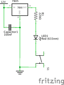
Circuit 2 Diagram

    • And it works

Circuit 2 Working

Building process

Since I have experience working on circuits and am familiar with how the breadboard works, our group does not have a problem building the circuit. However, we met with a few problems that make the circuit does not work in the beginning.

Problem 1: For the Voltage Regulator, we do not know which one is “in” and which one is “out.”

Solution: We tried to link them to power and see which one works.

Problem 2: The light is not on when the circuit is closed.

Solution: We used a multimeter to test the voltage between different parts of the circuit. Finally, we found out that we did not link the GND back to the negative electrode of the power.

Problem 3: The switch does not work. The LED is always on.

Solution: By using a multimeter to test the different sides of the switch, we found out that every two sides of this kind of switch are linked together. After understanding this mechanism, we turned the switch 90 degrees. It finally works.

Circuit 1:

Introduction

This circuit is built to work as a doorbell. When pressing the bottom, it is supposed to ring.

Components

    • 1 * Breadboard: to connect the components together.
    • 1 * LM7805 Voltage Regulator: to make power works and current stable.
    • 1 * Buzzer: to make sound
    • 1 * 100 nF (0.1uF) Capacitor: to make the current stable
    • 1 * Push-Button Switch: turn the doorbell on and off
    • 1 * 12-volt power supply: make sure the power works
    • 1 * Barrel Jack: make power works
    • Several Jumper Cables (Hook-up Wires): link components on the breadboard together.

Design and outcomes

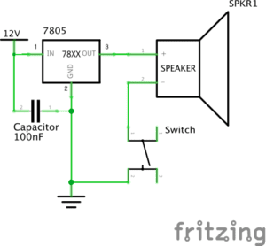
    • Following the instructions, we link these components like this.
Circuit 1 Diagram

    • And it works

Building process

On the basis of Circuit 2, we took out the LED and the resistor and replace them with buzzer. It works.

Circuit 3:

Introduction

This circuit is built to work as a Dimmable Lamp. We can turn the LED to different degrees of lightness.

Components:

besides what we have in Circuit 2, there are:

    • 1 * 10K ohm Variable Resistor (Potentiometer): to adjust the lightness of LED by turning the resistor to different ohm.
    • 1 * Arcade Button: another kind of switch.

Design and outcomes

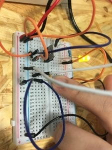
    • Following the instructions, we link these components like this.
Circuit 3 Diagram

    • And it works

Building process

On the basis of Circuit 2, we add a variable resistor into the circuit. Again, we do not know to link it into the circuit. We tried different ways and figured out the correct one. Afterward, we change the switch to the Arcade button. It works.

Reading question 1:

       According to “What Exactly is Interactivity?” the author thinks that interactivity requires “input, process, and output” (5) and “it responds to … reactions” (6). All three circuits meet these requirements. Let’s use “doorbell” as an example. One person presses the button, giving the information that “I’m waiting outside the door,” is “input.” Then the circuit close, meaning that it gets the information and do “process” on it. As a result, the bell rings as an “output.” Furthermore, as what the author means on “interactivity,” these circuits also function to entertain the users. At least, I think it’s quite interesting to press the button and make the doorbell rings with certain beats no matter whether this “interactivity” is “subjective” or not.

Reading question 2:

       According to the three projects that Zack Lieberman introduces, we can see that these projects perfectly applies his interaction design to Interactive Art by using physical computing. So, I would argue that “physical computing” is one essential approach to make an interactive idea come into interactive experiences that work in the real world. “EyeWriter” is one example. The software and hardware, regarding as “physical computing,” makes it possible for disabled to create work in a creative way. These technologies are the key to making the design of this project works. Without “physical computing,” it could only be an ideal model instead of existing art that can interact with people.

Works Cited

Crawford, “The Art of Interactive Design,” pp. 1-5.

Lieberman, Zach, “Zach Lieberman: Interactive Art,” PopTech, 2010.