Week 1: building circuits & soldering (Lee)–Katie

In the recitation, we are asked to build 3 simple circuits.  In high school I had some experience building the circuits but I never used a  bread broad. I used to see every wire I connected. The problem with bread broad is that I cannot see every wire, so the first step is to get familiar with how the bread broad is connected within.  The second step is to know what the materials look like. me After acknowledging these, it becomes easy for me and my partner to build the circuit.

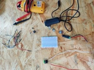
These are materials needed:

  • 1 * Breadboard
  • 1 * LM7805 Voltage Regulator
  • 1 * Buzzer
  • 1 * Push-Button Switch
  • 1 * Arcade Button
  • 1 * 220 ohm Resistor
  • 1 * 10K ohm Resistor
  • 1 * 10K ohm Variable Resistor (Potentiometer)
  • 1 * LED
  • 1 * 100 nF (0.1uF) Capacitor
  • 1 * 12 volt power supply
  • 1 * Barrel Jack
  • 1 * Multimeter
  • Several Jumper Cables (Hook-up Wires)

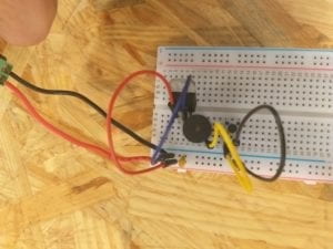
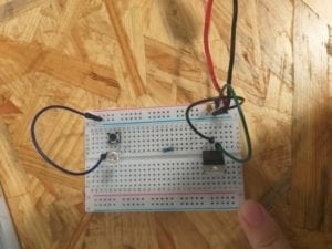
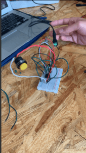
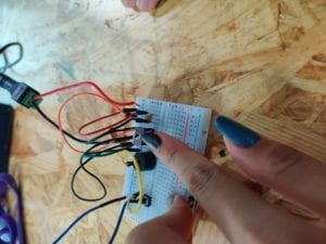
The first circuit we built:

As we are building, the first problem occurs is that we do not know how to make things grounded. We even want to connect the wire onto the floor. With the help of Inmi, we know that the ground is the cathode of the bread broad. And it’s worth noted that always use a darker color to ground.

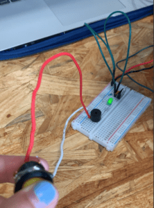
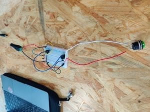
This is the second circuit:

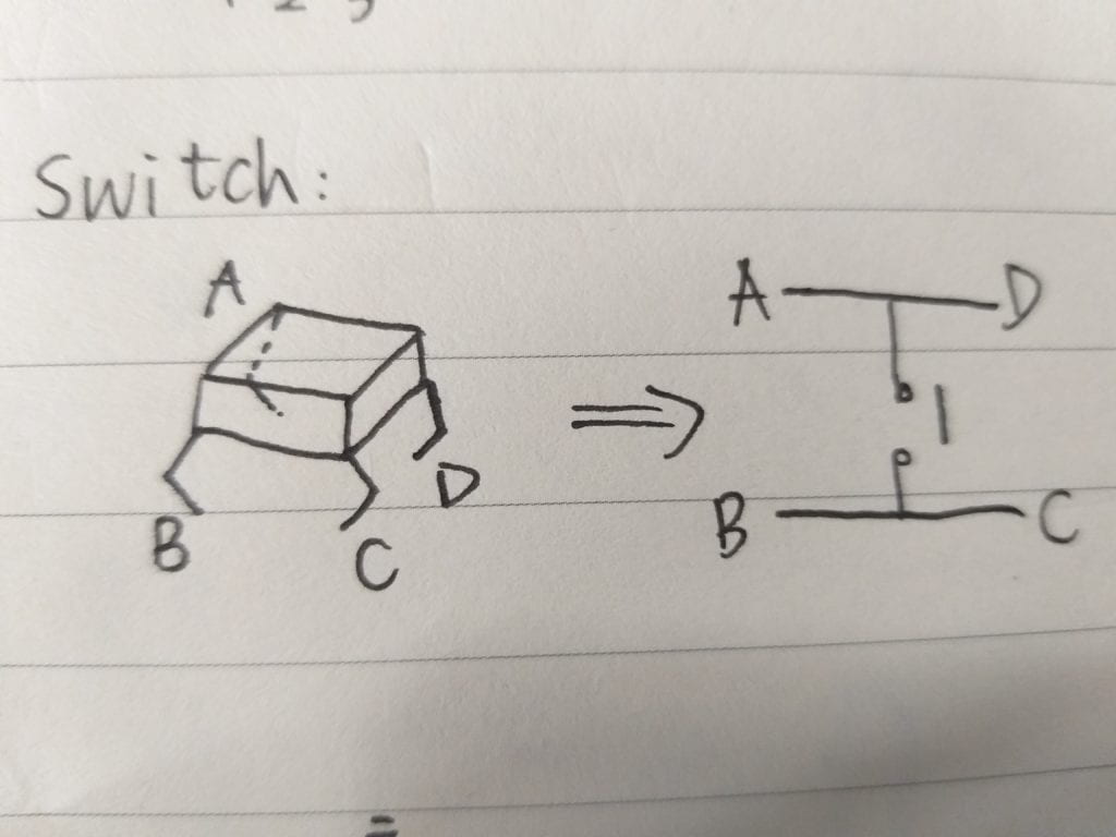
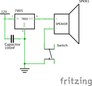
Another problem is how to put the switch. We think how we connect all the materials are right but the light is always on, it doesn’t control by the switches. Later after we looked at the diagram we found out that the four legs are not equal. A and D is connected and B and C is connected. You can only place the switch in a certain way. We then change the way we put the switch and it works. 

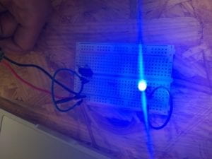
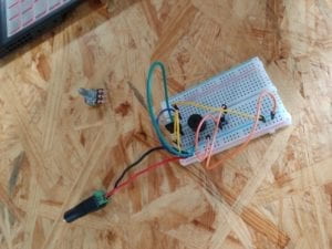
This is the third circuit we built:


Answer to the question: 1. Interaction is a process of act and react. That is to say, one throw a message to the other and the other one process the massage and throw it back.  When building circuits, we give the circuits messages and get feedback from it. If the light is not on or there’s no sound in the speaker, we will improve on our currently built. So it’s a way a interact.

2. Speaking to interaction and art, what most impressed me is teamlab’s work. I went to an exhibition of teamlab in  shanghai this summer. It was really beautiful and interactive.  The images on the wall will change according to your different pose and position.

Interaction Lab Recitation- Lillie Yao

Electronics & Soldering

Materials:

  • 1 * Breadboard
  • 1 * LM7805 Voltage Regulator
  • 1 * Buzzer
  • 1 * Push-Button Switch
  • 1 * Arcade Button
  • 1 * 220 ohm Resistor
  • 1 * 10K ohm Resistor
  • 1 * 10K ohm Variable Resistor (Potentiometer)
  • 1 * LED
  • 1 * 100 nF (0.1uF) Capacitor
  • 1 * 12 volt power supply
  • 1 * Barrel Jack
  • 1 * Multimeter
  • Several Jumper Cables (Hook-up Wires)

Introduction:

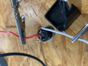
For soldering, we started out with a button, two wires, and a solder. Then, we had to trim the wires so that we could use the solder to melt the wires onto the button. We soldered the button together so that we would be able to use the button in our next projects. By doing this exercise, I learned how to solder and use the tool safely.

Exercise 1:  Door Bell

For this exercise, I learned about circuits and what the difference between ground and positive means on the breadboard. I used the breadboard to connect different wires and lastly to the button that I made. The final result was when I plugged the breadboard into the power, it made a ringing sound.doorbell

Exercise 2: Lamp

In this exercise, I basically did the same exact thing with the button except this time, I attached a LED light to it as well. The end result is when I pressed the button/switch, the LED light would turn on and off. This was more difficult because I had to figure out how to use a resistor the correct way.

lamp

Reflection:

I loved this lab, it was so fun and interesting for me because I’ve never done anything like this before. It was a cool experience being able to connect wires on the breadboard and so satisfying to be able to achieve and finish the exercises on my own. By doing this lab, I learned a lot about circuits and how to tell if the wire should go in the positive or negative; how to read a diagram; how resistors and capacitors work; and how to connect everything to a breadboard.

Questions:

  1. I think the circuits that I built are an example of interactivity because they made me think outside of the box about how to create a working circuit. Another reason that the circuit is interactive is because someone has to press the button/switch in order for it to turn on or off.

Recitation 1: Electronics and Soldering by Tya Wang

In the first recitation, we tried soldering in person to take a peek at how circuits are connected together. Also, we built three circuits on a breadboard with detachable wires and parts in order to learn about how electricity and breadboards work. These exercises ware both a warm-up for this course and a foundation of working with Arduino boards.

Circuits

Materials:

  • 1 * Breadboard
  • 1 * LM7805 Voltage Regulator
  • 1 * Buzzer
  • 1 * Push-Button Switch
  • 1 * Arcade Button
  • 1 * 220 ohm Resistor
  • 1 * 10K ohm Resistor
  • 1 * 10K ohm Variable Resistor (Potentiometer)
  • 1 * LED
  • 1 * 100 nF (0.1uF) Capacitor
  • 1 * 12 volt power supply
  • 1 * Barrel Jack
  • 1 * Multimeter
  • Several Jumper Cables (Hook-up Wires)

Below is a picture of all the materials:

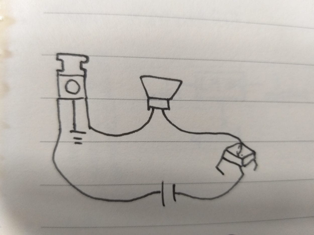
Circuit 1: Door bell

doorbell

Interestingly, the first exercise for me and my partner was the most difficult because neither of us understood how a breadboard works. At first, we connected power to one side of the board and ground to the other side, because I thought both sides would be the same. And we also put the electronic parts parallel with the rows that electricity flows through. We didn’t understand what was going on until the instructor explained to us that the lines are connected electronically and the two sides of the board are not connected at all. These are two of the most important takeaways from this recitation session.

This is how our final circuit looks like:

We struggled to make out the difference between the three feet of the transistor. When electricity is flowing through, the temperature on the transistor may be very high.

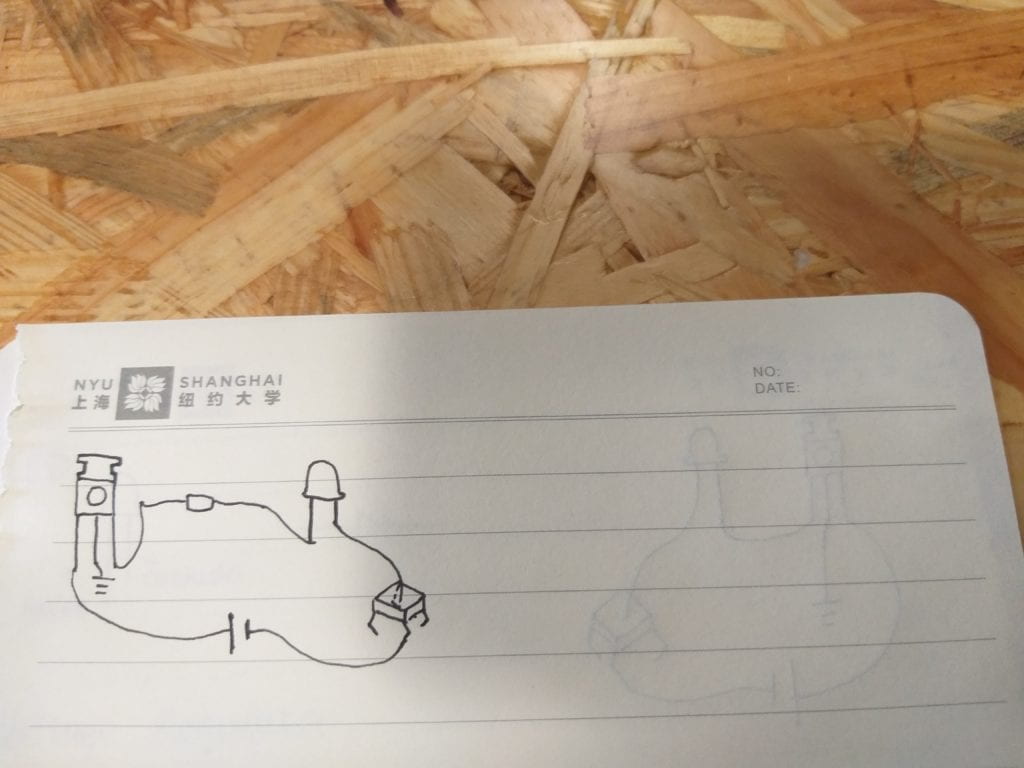
Circuit 2:  Lamp

lamp

After understanding how circuits and breadboards work, building the second circuit became way easier for us.  We used the button we made during soldering into the circuit to make switching it on and off easier. We don’t need to limit ourselves to the factory manufactured electronic parts. We can actually design and make parts tailored to our preference.

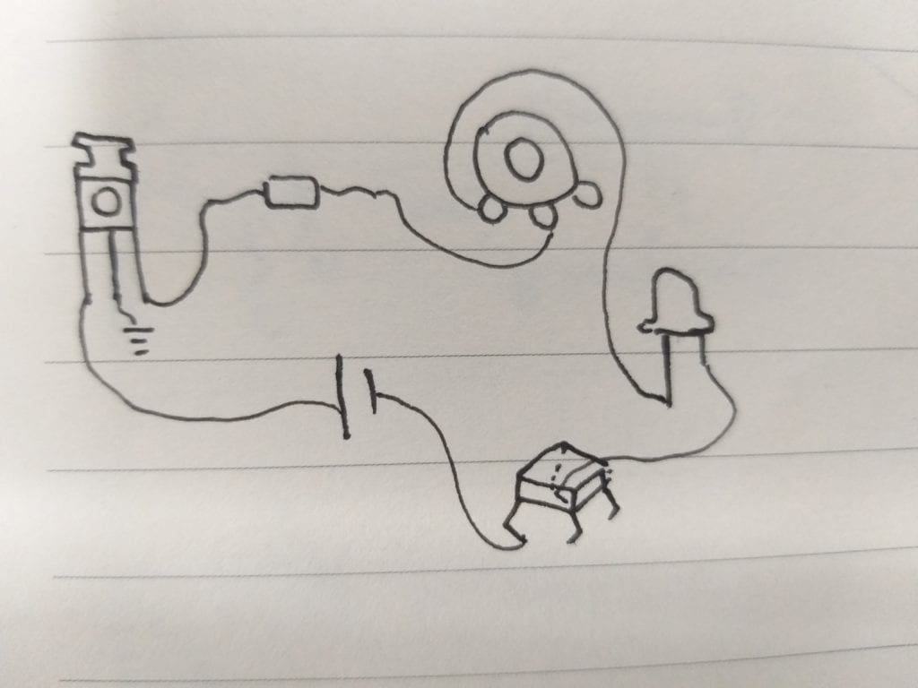
We didn’t really have time for the third circuit in class. But we talked through how to use a variable resistor in this diagram.

Reflections

After reading The Art of Interactive Design, in what way do you think that the circuits you built today include interactivity? Please explain your answer.

I think that the circuit respond to human’s switching and off immediately by its output devices. The three steps of the process of using these devices fit into the model of interactivity given by the author: the circuit first wait for the user to give an instruction of what to do and record the signals, the user gives his/her decision of whether to switch on or off, and finally, the circuit gets the instruction and executes it. However, according to the definition, I think a complete interactive product need to have more back and forth in these responses and the two parties’, and the expression of ideas and information should be more complicated than a simple on/off.

How can Interaction Design and Physical Computing be used to create Interactive Art? You can reference Zack Lieberman’s video or any other artist that you know .

In Zack Lieberman’s video, the device has a sensor attached on it to record the motion of human. And by computing and analyze the data gathered by these sensors, an output device can then perform another motion or give some feedback. In the case of eyewriter, the feedback would be the image generated by the software or the picture projected onto the building. Art can be created this way in a sense that either interaction design and physical computing use technology to help human create art in the traditional forms, or their output itself represent a new type of art.

Recitation 1: Electronics and Soldering – Zhao Yang (zy1190)


Overview

In the first interaction lab recitation class, we were required to build three different circuits on the breadboard and solder one button. It was my first time using these materials to build the circuits. Even though we encountered some problems when we built the circuits, we still finish all the tasks that we were required to do and we even make something beyond the original task. Here is the documentation of some process in the recitation class. 

Materials

  • 1 * Breadboard
  • 1 * LM7805 Voltage Regulator
  • 1 * Buzzer
  • 1 * Push-Button Switch
  • 1 * Arcade Button
  • 1 * 220 ohm Resistor
  • 1 * 10K ohm Resistor
  • 1 * 10K ohm Variable Resistor (Potentiometer)
  • 1 * LED
  • 1 * 100 nF (0.1uF) Capacitor
  • 1 * 12 volt power supply
  • 1 * Barrel Jack
  • 1 * Multimeter
  • Several Jumper Cables (Hook-up Wires)

Circuit 1:

The first circuit is a doorbell. If we pressed the button, the doorbell would be turned on.

 Although it’s an easy circuit, we still encountered some problems when we build the circuit. It was the first time we used the breadboard to build the circuit so we were not

familiar with the use of the breadboard. The first circuit we built was not even a closed circuit. So it didn’t work. After asking the learning assistant for the use of breadboard, we succeeded in finishing the first circuit. And here are the video and photo of our first circuit. 

Circuit 2 & 3

For the processes of the second circuit and the third circuit, they were much more smooth than the first one. However, as the circuits became more difficult and complicated, we had to deal with the problem of the order of the jumper cables. Since the number of cables became more, we needed to make everything in order. I realized that when building the circuits, we should keep cables not entangled with other cables so that when we encounter some problems in the circuits we can easily fix it. In addition, understanding the principles of all the electronic materials are also important for us to successfully build a circuit. And here are videos of the second and the third circuits. 

Additional Work

After finishing all the tasks we were asked to do. We used the materials we had to build a new circuit which includes the speaker and the LED. The process of building a new circuit was pretty fun. Moreover, the new circuit we built is also meaningful. For those who are trapped because of the earthquake, it can give them more possibilities to be rescued than those who have nothing to help them. For example, if you are trapped under a building, you can first press the button to turn on the speaker, then other people can easily get your possible location after hearing the sound. You can keep pressing the button to turn on the light so that other people can get your exact location after seeing the lights. Then you can survive in the earthquake. And here is the video of our own circuit. And in this video, I was also conveying the signal of “SOS”. 

Reflection

In the first recitation class, I didn’t encounter anything that really confused me. We had dealt with all the problems we had during the process of building the circuit and soldering the button. Besides, even though the circuits we built in the recitation class were simple, we have to be careful of the electricity every time we build circuits. 

Reading Questions

  1. The main idea of The Art of Interactive Design is that interactivity contains three parts: input, processing, and output. The circuits we built included interactivity in the way that after we finished building it, we pressed the button and then we could hear the sound or see the light. The action of pressing the button can be seen as the input. The flow of the electricity in the circuits can be seen as processing. And the sound we heard and the light we saw can be seen as the output of the circuits. 
  2. In my opinion, interaction design is like the foundation of Interactive Art. And physical computing is like the approach to achieving all the requirements of the interaction design. For example, if we see Interactive Art as a building, then interaction design is the base of the building and physical computing is the bricks of the building. To create Interactive Art, we need to first come up with the idea of what we want to create. This process can be called interaction design. Then we can use both hardware and software to turn the interaction design into reality. This step is physical computing. Interactive Art cannot be called Interactive Art without either interaction design or physical computing. 

Interaction Lab: Isabel Brack Recitation 1 Documentation

Introduction:

During the first recitation I experienced many new processes and problem solving opportunities, including building various circuits and soldering.

Circuit 1:
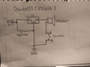
Circuit 1: The Doorbell

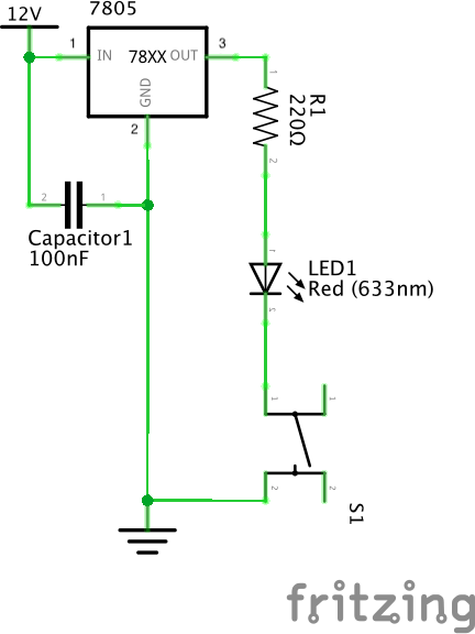
The doorbell circuit diagram included a 12V battery, or in our case a power source that is connected to an outlet. The 12V battery is the source of electricity to the entire circuit, providing the electrons that will run throughout the closed circuit. The 12V contained a negative and positive wire, the positive to provide the flow of electrons and the negative wire will connect to other components of the circuit that need to be grounded. The capacitor connects to the positive wire of the 12V and also to the negative 12V wire to ground it. The capacitor retains and stores electrical energy. The voltage regulator has the connecting components: an input, output, and grounding component. The input metal prong connects to the positive wire from the 12V, the output metal prong connects to the speaker, and the grounding metal prong connects to the negative wire from the 12V to ground it along with the capacitor. The voltage regulator is a mechanism intended to maintain the circuit’s voltage at a constant voltage. The speaker connects to the output prong of the voltage regulator and also connects to the switch. The speaker is the mechanism that produces sound when the circuit is closed and the electrons flow through the circuit, powering the speaker. The switch connects both to the speaker and to the negative wire of the 12V power source to ground the switch. The switch (in our case a button) will close the circuit when the switch is closed and leave the circuit open when the switch is open. As long as the power source is connected the switch determines whether or not the circuit is closed and electrons can flow throughout the circuit to power the speaker. With the doorbell circuit we ran into issues with the orientation of the switch as the connecting wires must be precise. We also ran into an issue with the switch not reaching the bottom of the breadboard the metal prongs were bent too much and therefore did not fit easily into their proper holes. For this circuit it made the connection of the speaker spotty and therefore even though the switch was closed when we completed the circuit the sound went in and out because the prongs did not connect to the bottom of the breadboard. For the next circuits we tried to ensure better connection between each component and the breadboard. We also switched to the arcade switch for the final two circuits because it connected better to our breadboard.

Circuit 2: The Lamp
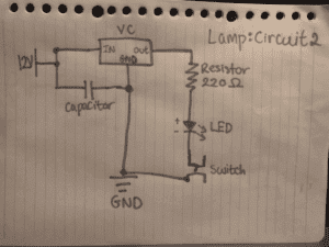
Circuit 2: The lamp

For the second circuit, the lamp circuit ,we used the base and similar structure of the circuit and altered the parts in the circuit that were different, specifically adding the resistor, the LED, and the arcade switch (for better connection). The power source, voltage regulator, and resistor all stayed the same regarding orientation on the breadboard. Differing from the Doorbell circuit, we added a resistor to the circuit connecting it to the output of the voltage resistor. We also connected the resistor to the LED’s positive wire (the longer wire end). The 220 Ohms resistor reduces the voltage to control the flow of electrons to the LED which requires less voltage the power source provides. The LED is a light with positive and negative wires. The LED lights up when the circuit is closed as the flow of electrons powers it. The arcade switch was put in place as the normal switch but we did not dim the light using the different settings of the arcade switch. This switch took a long time for us to build because we were interrupted to take the soldering workshop, which for our groups took much time because our machine was not hot enough to start and therefore did not heat up the metal enough to join the switch and the wire. With this circuit we ran into orientation issues on which wire to connect to which prong of the voltage regulator. To solve this problem we consulted the images at the bottom of the instructions that had a key for how the voltage regulator should be connected.

Circuit 3: The Dimmer Lamp
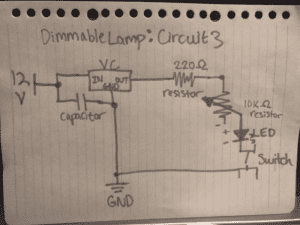
Circuit 3: The Dimmer Lamp

The last circuit was our Dimmer Lamp circuit. The circuit was similar to the previous lamp circuit but also included a second resistor, 10 Ohms, the potentiometer. The potentiometer is a resistor that reduces the voltage of the circuit through its three terminal mechanisms. One prong is connected to the first resistor, the second prong is connected LED, and the third prong is grounded. At first we ran into trouble with which prong to connect to which component but the diagram at the bottom of the recitation instructions outlined the correct method, helping us fix our orientation issues.

Process and Problems:

All the circuits worked. The doorbell circuit worked on the first try. Both the dimmer circuit and the lamp circuit required a bit of trial and error, as we fixed the resistor’s position in the lamp circuit and the potentiometer’s connections on the dimmer circuit. Our main difficulties with the circuits where with our switch not connecting fill to the breadboard, which we fixed by changing the switch we used for the second two circuits. The orientation of certain components on our breadboard was also challenging, as some components like the potentiometer only worked with certain orientation and connections of certain metal prongs to the LED, resistor, and grounding. In addition to a few minor procedural issues we faced in the construction process, as we built the last circuit (the dimmer), we were only able to test one level on the arcade switch. Our circuit did work in theory but we were only able to test one of the three brightness, partially for time constraints, and partially because we could not get the switch to change brightness.

Question 1:

The circuit would, in theory, be considered interactive as there was an interaction between the person pressing the button and the switch closing the circuit to perform a task, whether that be lighting up or producing a sound. The original initiating action is the human pressing the button. As a reaction to the button being pressed the switch closes the circuit, which intern produces an output of sound or light. In the “What exactly is Interaction?” reading, the author mentions different degrees of interaction (6). As a circuit controlled by a button/arcade button, the circuit does have some degree of interactivity as two interacting parties (the circuit and human) both have actions and reactions to the other party, but they are not as complex interaction as two humans would have, being able to respond in different manners based on their best judgment of the situation.

Question 2:

Daniel Rozin’s wooden mirror is a more complex interaction between a human and the mirror itself requiring multiple steps to perform the interaction. The human has some sort of movement and the camera or sensors of the mirror record those movements, sending a signal to the different motors powering each wood panel. As a result of that signal, the motors move to change the angle of the wood and allow for different values to show the image being mirrored. The light reflects off of different panels of angled wood to form different values and make the human image. Interactive design is used throughout the wooden mirror, especially considering the sensors and cameras that map the image of the human and then translate those signals so the motors on each wooden block can move and form the human image based on light reflection.

Physical computing uses software and hardware to create interactive systems, which is how many interactive art projects program their project combining coding and software with hardware, tangible microcontrollers and devices connecting the software and instructions from coding with the physical controllers that control the motors just like in the wooden mirror. The software instructs the project to take in and process the image from the sensors and camera converting that into data and then instructing the tangible motors and microcontrollers to signal movement of each wooden block.