Recitation 1: Build Circuits & Solder by ChangZhen from Inmi’s Session

1. Solder

With Kriss and Katie.

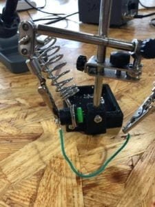
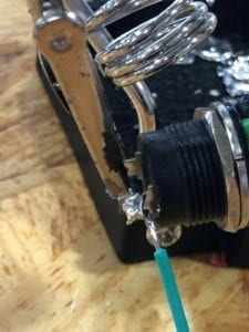
We held, cut or peeled the wire using different parts of the clamp. After peeling the wire to leave its metal core exposed, we fixed it and the switch onto a clip device, flipped on the soldering machine, set its temperature about just higher than half the dial and pulled up the soldering pen. Teammate fetched solder, which we got to contact the pen near above the connection. Soon the solder liquified, fell on the connection and became part of the connection when it cooled.

2. Build Circuits

With Katie.

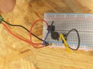
1) Door Bell

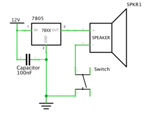
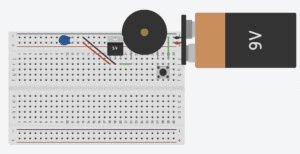
There were issues on what’s to ground. Then we knew that the ground is defined to be 0V, and so is the negative polar. Then we matched connections with the same potentials.

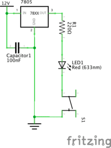
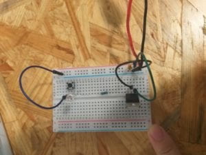
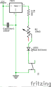
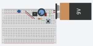
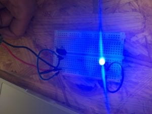
2) Lamp

(Please don’t care about the LED polarity in the second picture since Tinkercad can’t flip a component.)

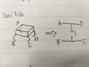
There were issues on the structure of the switch. As is drawn by partner Katie, showing below what’s inside a switch. AD and BC terminals are connected; we tell them by the convex bar at the switch’s bottom. Terminal I shouldn’t be shortened.

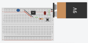
3) Dimmable Lamp

(Please don’t care about the LED polarity in the second picture since Tinkercad can’t flip a component.)

3. Answers to Questions

1) After reading The Art of Interactive Design, in what way do you think that the circuits you built today include interactivity?

Interaction consists of the conversation between the machine and the player. It’ s a circulation of real-time action and reaction. We switch close, and the circuits would scream, gleam or do nothing when built, to have us know if they were OK or wrongly built, by which outcome we decide to correct or accept them. Knobbing the potential meter to change the dimness of LED in the third circuit is also interaction. We knob, LED changes, and we judge how much the light change is proper, and we knob…

2) How can Interaction Design and Physical Computing be used to create Interactive Art?

Interaction design is added to the idea of getting beyond screen and keyboard. By physical computing, sensor inputs and multiple outputs realize the design. We can make interactive art instantly responding. One characteristic of the artwork is that it’s dynamic, it’s lively, and it’s intelligent.

Recitation 2: Arduino Basics by Tya Wang

We got our own Arduino kits in this recitation. I felt so good building these devices using my materials although I’m still assembling circuits based on instructors’ ideas. This time we combined programming and working on circuits to carry out more complicated projects. Since Inmi told us in class that we are going to try out the if clauses in this recitation and I’m worried that I might be overwhelmed by all the logic and syntax, I previewed the codes before recitation. This has made this recitation pretty smooth and efficient for me. I don’t have to try understanding everything while paying attention to the physical electronic parts. I think this will always be a great strategy to take when it comes to coding that I’m not proficient in.

Circuits

Materials

1 * Arduino Uno
1 * USB A to B cable
1 * breadboard
1 * buzzer
2 * LEDs
2 * 220-ohm resistors
2 * 10K ohm resistors
2 * pushbuttons
A handful of jumper cables
2 * arcade buttons

Circuit 1: Fading
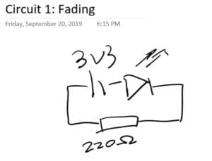
We directly used the example code from Arduino after talking about what it does.  We both agreed that this code is walking the led back and forth from dim to bright by changing the PWM value sent to it using an if clause to see whether the value should go up or down, changing the brightness of light in the meantime. Therefore, we did a pretty simple circuit: linking LED to pin 9 as the example code suggests, using a 220-ohm resistor and plugging in the power source and it worked–that simple:/

Circuit 2: Buzzer

Still, the most challenging part of circuit 2 is understanding the code, since there is a new clause of for in it, and uses the function tone() that asks buzzers play music. Circuit-wise, we just needed to notice that the buzzer is polarized and pay attention to which direction electricity flows.

We searched online and it says for in C works this way:

for ( init; condition; increment ) {
   statement(s);
}

So we understood that the example code is trying to play the melody once by iterating over each note’s melody and duration by using the tone() function every time the board is reset. We looked up the reference in the toolbar, and we noticed that the third argument in tone() is optional, therefore we could also stop the buzzer playing using noTone() function. This means we can also write our song as to let the buzzer play as long as we could make out each note in it. 

Circuit 3&4: Speed game

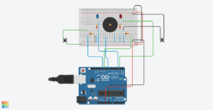
The third circuit is a fun but complicated one, especially when you put into the third and fourth players. But after we figured the code out, it seemed quite simple especially when the blueprint of the circuit is already there to be referred. This is what our circuit for two players looked like at first. The serial panel is only showing the record of player 01 pressing the button, and that’s when we realized an error occurred when we were building the left side of the circuit. We did a little troubleshoot around the second button, and it didn’t take us long to find out it was just a minor mistake of connecting both sides of the button to ground. It’s always more efficient to figure out what’s wrong if you have a primary idea of which part of the project is troublesome.
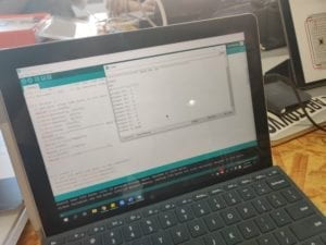
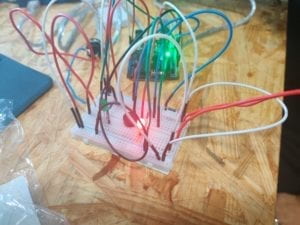
After we fixed the problem, the circuit worked pretty and smooth.

For the last 15 minutes of the recitation, we worked together with the group of Lisa Moon to build the game for 4 players. I and Lisa did the same change to the code, which was basically copying and pasting lines to assign new pins for the other 2 buttons and to record if player 3 and 4 have pressed their button, since the original logic of the code is to check when player 01 press the button and win 1 point, whether he/she has reached 10 points in all in order to champion the game, provided the other players have not championed yet. And then player 02, 03, 04… (So the program is not actually fair because if there are multiple players pressing the button exact the same time, whoever is checked first by the program always gets 1 more point) Therefore, we just need to add the sentences for player 03 and 04 to make the program work.

Our final result is quite wild.

Reflections

Reflect how you use technology in your daily life and on the circuits you just built. Use the text Physical Computing and your own observations to define interaction.

Interaction is the process in which two parties involved repeatedly send information through media such as words, sound, image, physical movements, etc while receiving the other’s information simultaneously. The more types of media are involved in the communication of information, the more interactive a relationship is.

Why did we use the 10K resistor with the push button?

Because the push button does not has ohms on its own. Since the voltage is how large we chose it, the smaller the resistor value is, the stronger the current it. In order not to fry the button with too strong a current, we need to put a resistor with a large value into the circuit.

If you have 100,000 LEDs of any brightness and color at your disposal, what would you make and where would you put it?

I think I will find a vacant space in the countryside of Shanghai, lay them on the ground into aircraft lanes, and run an open bid to let the company that offers the most money to build an airport next to it.
Recitation 2: Arduino Basics by Ian (You Xu)

In this week’s recitation, we created three circuits and used the reference code to run the circuit.

Circuit 1:

Following the instruction, we quickly built the circuit by linking a LED and a resistor to the Arduino.

We copied the code and made the LED blink successfully. Since I have experience coding Python, it’s easy for me to understand how the “for” and “if” causes work in the code.

Circuit 2:

The instruction for building the circuit is also very straight forward. We did not meet any difficulties while building the circuit.

Circuit 2

When trying to run the code, it says that the system cannot find the file “pitches.h.” Then we realized that we may need to create this file by ourselves as it is explained in the Arduino website. Since I have coding experience, I can roughly tell what the code means. However, since I know nothing about music and tone, I do not know how the melody works. I guess it’s not a big deal. In the end, the program runs successfully.

We also think it may be a good idea if we copy the code to the “void loop” function to make the melody playing repeatedly.

Circuit 3:

The circuit building is a little complex. We spent some time to finish it. Following the instruction, we also finished it quickly. And we change the original button with Arcade button. Following is the actual schematic.

Circuit 3 Schematic

We directly run the code and played the game multiple times.

Circuit 3

Circuit 4:

We are about to challenge circuit 4 with another group. However, we realized that while building the circuit is easy, the coding part may take some time to finish. Since we only have a few minutes left, we did not finish doing circuit 4.

Question 1:

Nowadays, we have already in an environment that is surrounded by computers. We use our phones every day. We take elevators. We wait for traffic lights. All these things matter with computer. The computing abilities of computer make our life easier by interacting with us even we do not notice.

According to Igoe and O’sulliven’s Introduction to Physical Computing, our interaction with computers consists of three parts – “input, output, and processing” (XX). Using circuit 3 as an example. We input our operation by pressing the bottom. The computer tells the result of the game as a response, in the end, regarded as output. As Igoe and O’sulliven say, “input and output are the physical parts of physical computing” that intuitively we can see. The magical part behind it is the process for the computer to do processing for the input and generate the output. This part requires algorithm and programming, which is an essential part of the computer to think like a human.

Works Cited

Igoe and O’sullivan, “Introduction,” Introduction to Physical Computing.

Question 2:

Compare to 220Ω, Higher R enables a lower current to pass the circuit. This can make the circuit works safer.

Question 3:

I would like to make it a digital mirror around a dark room. The color and brightness can show the mood and mentality of the person standing in front of it. Brighter color and higher brightness indicate a more positive state.

Vivien Hao–Documentation Post 1

Components in the circuits: Resistor, LED, capacitor, voltage regulator, variable resistor, push-button, speaker, power, wire.

Resistor: A resistor is a two-terminal electrical component that resists the flow of electricity and can be used to control the flow of current.

LED: a light that examines the buildups of the circuit. If the circuit is built up successfully then the LED should blink.

Capacitors: store electricity and can also be used to stabilize the flow of electricity. Voltage regulator: it is used to regulate voltage levels.

Variable resistor: attached to a knob that can output an adjustable voltage.

Push-button: it is used to trigger the system.

Speaker: it is used to play sounds when electricity is pushed through wires.

Power: Gives the circuit abilities to function. Such as producing sounds, blink, etc.

Wire: Carries power from one point to another point.

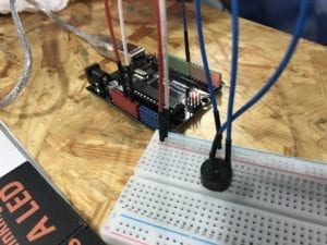
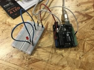
Pictures: Door Bell      

  Lamp      

 Dimmable Lamp

Throughout the entire building circuits process, we have encountered several obstacles where the circuits did not function properly. For example, in the doorbell circuit, the speaker did not work at first. We accidentally connected the wires in the wrong direction. We asked the LAs for help. And they kindly reminded us that we always need to connect the wires back to the ground.

The three circuits we have built during recitation time clearly show interactivity. Each group member had to do hands-on works in order to successfully build the circuits. We have to connect wires, insert all the components that each circuit needs to have. For the doorbell circuit, we had to press the push button in order for the circuit to produce an audio sound.

Interaction designs are usually physically made by the artist. In Zack Lieberman’s video, he illustrated an example of how they helped a paralyzed graffiti artist to keep on drawing while he is in a hospital room. They built up a system that allowed the artist to just make eye movements to draw. And the team would project those drawing on many walls throughout the city. He said at the end of the video “We’re helping people to breathe.” Interaction designs help to open up possibilities in impossible situations.

Recitation 1: Electronics & Soldering by Yu Yan (Sonny)

Introduction:

In the recitation of the first week, we learned how to build circuits to make different components working using the breadboard. We also learned how to solder so that separate components can connect to each other into one part. The details are as followed.

Materials:

  • 1 * Breadboard
  • 1 * LM7805 Voltage Regulator
  • 1 * Buzzer
  • 1 * Push-Button Switch
  • 1 * Arcade Button
  • 1 * 220 ohm Resistor
  • 1 * 10K ohm Resistor
  • 1 * 10K ohm Variable Resistor (Potentiometer)
  • 1 * LED
  • 1 * 100 nF (0.1uF) Capacitor
  • 1 * 12 volt power supply
  • 1 * Barrel Jack
  • 1 * Multimeter
  • Several Jumper Cables (Hook-up Wires)

Circuit 1: Doorbell

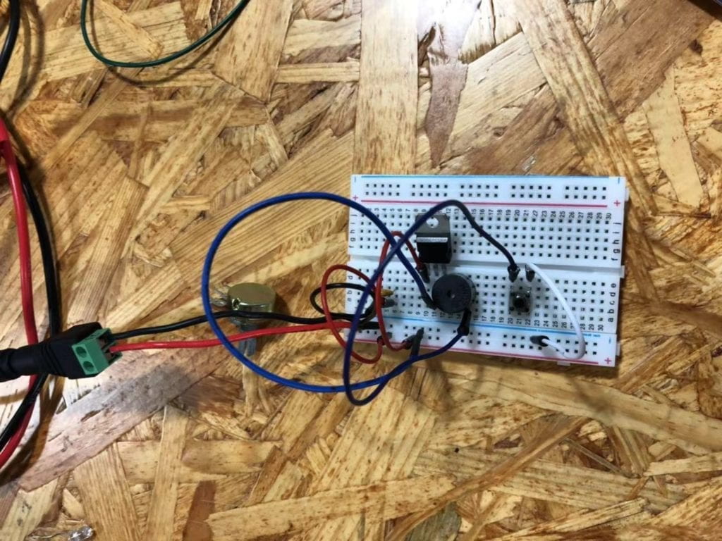
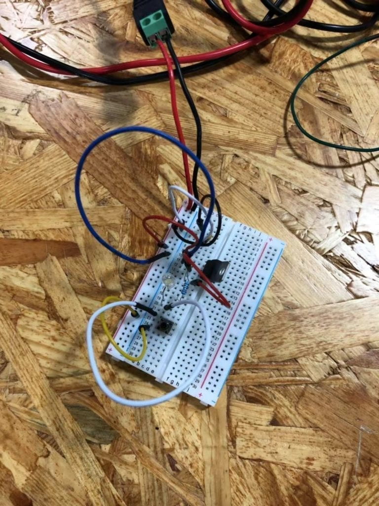
This is the doorbell circuit that my partner and I built based on the given circuit. As shown in the picture, we used a capacitor, a voltage regulator, a push-button, a speaker and several wires to build the circuit. We used the capacitor to stabilize and smooth the flow of electricity.  The voltage regulator is used to maintain a constant voltage level.  We used the push-button as the switch to make the circuit work when pressing it and cut when releasing it. The speaker is the output of the circuit and it would make a sound when the circuit is connected with the power. Wires help to connect different components of the circuit. At first, we built a full circuit and connected it to the power. However, something happened when we pressed the button. After we asked the instructor for help, we realized that the circuit is too compact that there was too much electricity going through the circuit. Then we made some changes to the circuit, and it worked finally. The following video can show you how the speaker circuit worked.

Circuit 2: Lamp

Compared to the previous circuit, the output of this circuit changed from a speaker to a lamp. We used a capacitor, a voltage regulator, a 220 ohm resistor, a lamp, a push-button switch and several wires to build the circuit. The capacitor, the voltage regulator, wires and the push-button switch play the same role as the previous circuit. The resistor is used to control the flow of current.  The lamp is the output of the circuit and there would be light when the circuit is connected with the power. After dealing with the first circuit, we felt easier to make this one. Finally, by following the given circuit diagram, we built the circuit successfully. The following video is to show you how the circuit works.

Soldering

Our task for soldering is to solder two wires onto a button. We cut the wire, peeled out its skin, and then we used the soldering apparatus to solder the wires onto the button so that those wires would not fall off easily and be able to connect the button to the breadboard steadily as well. It was a really cool experience to solder things together. The following picture and video can show you how we do this.

Reading Response

Question 1:

I think the circuit that I built can be a low level of interactivity. Since both the speaker and the lamp is not alive, and they can only work when connecting to the power, they just responded to my actions/input such as pressing the push-button switch to the current flew into the circuit. As you can see, the whole process of input, process and output has been completed. So I think the circuit includes interactivity.

Question 2:

Interaction Design and Physical Computing can design games that involve with people’s interactions, make different forms of art, and build tools to help people create Interactive Art. In Zack Lieberman’s video, plenty examples are given such as moving objects that they draw, driving cars to write, and making special classes to help paralyzed people draw. As Zack said, using Interaction Design and Physical Computing to help people create art is so meaningful, just like “helping people take a breath”.