Recitation 2: Build Circuits with Arduino Control by ChangZhen from Inmi’s Session

1. Build Circuits

With Rannan

1) Fading Lamp

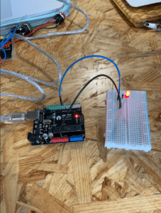
We learnt that power could directly come into the breadboard on the positive and negative lines like the last recitation and could also come through Arduino uno to power the components.

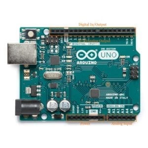
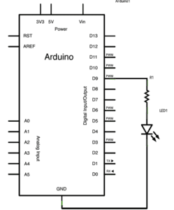
Roughly like the picture below, we got clear about the Arduino parts. And we knew that GND in digital in/output group works the same as that in power group.

2) ToneMelody

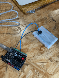
It sounded but was not playing the expected melody. We failed to use the code, maybe…

We learnt the importance of selecting the board/uno and port/the USB one.

3) Speed Game

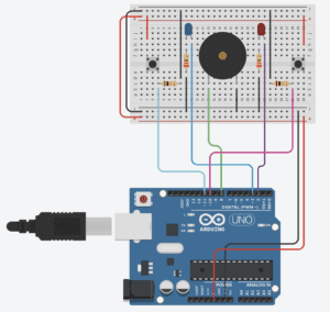
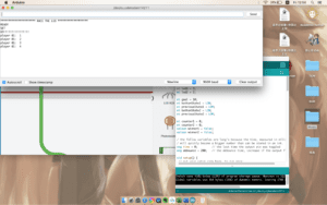
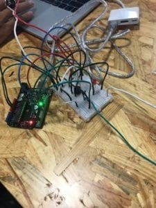
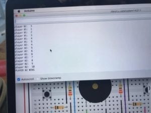
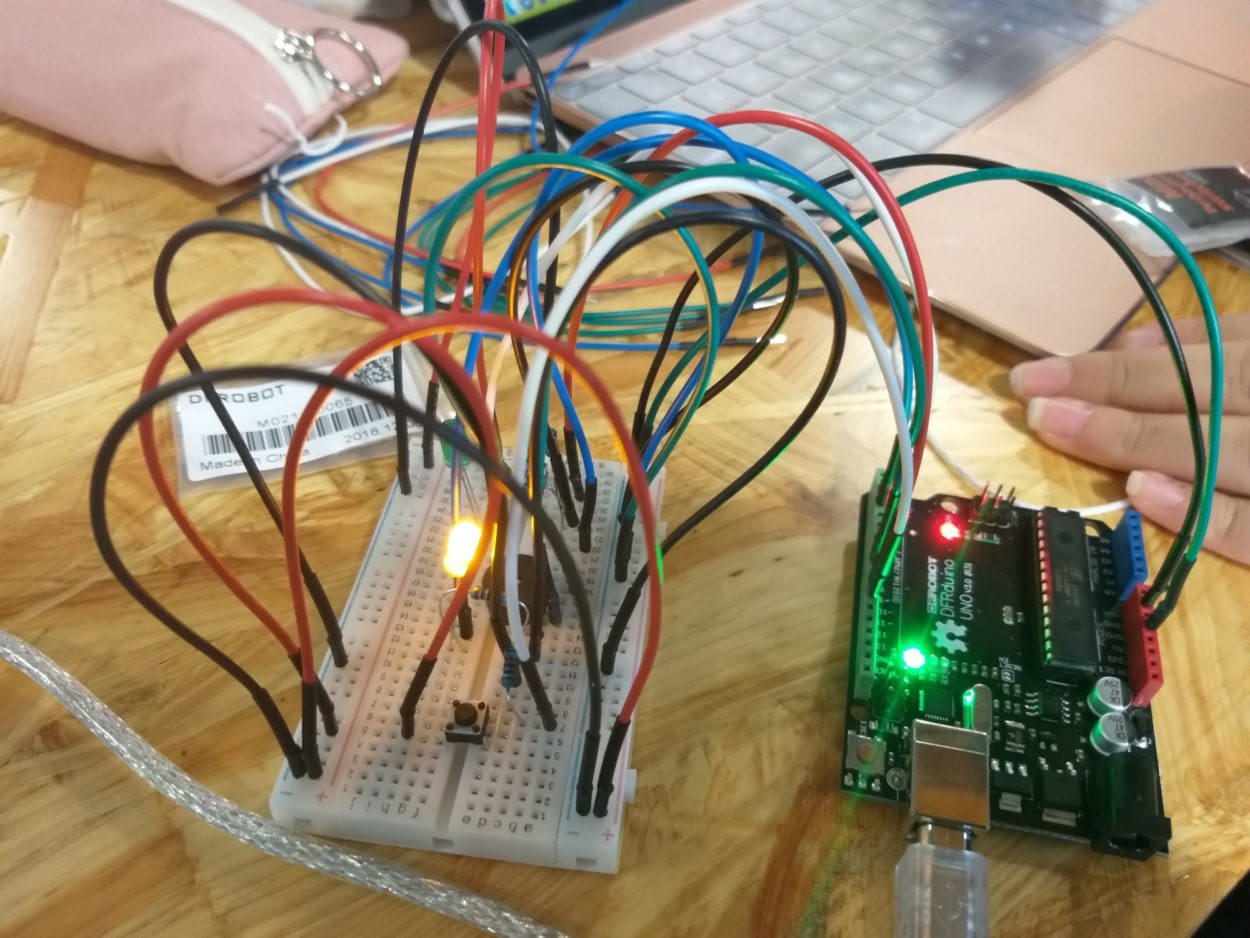
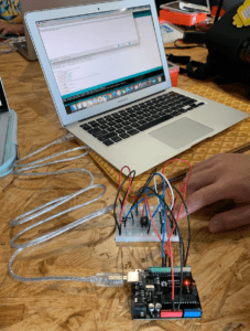
We separate the circuit into two parts and built that on the own side. Since we used switches outside the breadboard instead of the small button attached there, we flexibly handled the connections. But as we tested, only one side was counting the hits as shown below.

Then we checked and repaired the circuit from a wrong connection. And done.

2. Answers to Questions

1) Reflect how you use technology in your daily life and on the circuits you just built? Use the text Physical Computing and your own observations to define interaction?

I mainly use hands to input and eyes and ears to receive the output with tech devices. This speed game circuit receives my push and give me output by my multiple senses. The former two circuits still are limited to hands, eyes and ears.

Input, processing and output, these steps of an interaction via technological devices makes lifeless computing machines lively and friendly to us.

2) Why did we use the 10K resistor with the push button?

When switch off, the circuit is open and nothing goes to 11 or 10; then Arduino will be confused if there is no signal in.

3) If you have 100,000 LEDs of any brightness and color at your disposal, what would you make and where would you put it?

A screen. Where a screen is needed, say, PC, phone and ads board…

Recitation 3: Sensors by Isabel Brack

Overview

Overall, this circuit was the most complex so far this semester, not in the amount of wires and connections, but the most tweaking and altering of the code to adapt an Arduino analog in out serial code (because we used the LED as an indicator on whether there was or was not moisture).  We first tested the moisture sensor with code that the moisture sensor link provides, testing the wire hook up and reading the serial monitor. Then we mapped it to an LED and later Servo.

Moisture Sensor Mapped to a LED
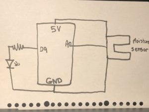
Hand Drawn Circuit Schematic Moisture Sensor LED Mapping

The circuit itself to set up was not too difficult. The moisture sensor connected to the A0 pin, the 5V and the ground. The LED connected to the resistor which connected to the digital 9 pin. The LED also connected to the ground. For the code, we took the example code Analog In Out Serial, which we previously have used to map a potentiometer to an LED. We also had to map the moisture sensor to the light, which was difficult to test its max value or input scale, unlike the potentiometer which is quite easy to test its maximum and minimum. We tested the moisture sensor in the air, on the back of our hands, on our palms, and in a wet paper towel, the highest reading I recorded was almost 700 (although it was restricted to what we personally found), the lowest was 0 in the air and the back of our hands, the palm ranged from about 25- 230. We mapped this to the LED which was 0-255 and read the serial monitor for showing us moisture (input) and light (output), which we relabeled using serial.print. As the sensor recorded moisture the light came on and off at varying brightnesses.

Video of Working Circuit:

In the video we added a bit of water to the palms of our hands to make them damp/moist.

Moisture Sensor Mapped to Servo
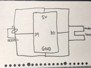
Hand Drawn Circuit Schematic  for Moisture Sensor Mapping to Servo

We also mapped the moisture sensor to the Servo motor to test a second output. For this Servo connected to pin 9, 5V and ground and the moisture sensor stayed the same. As we introduced moisture to the senior with the same methods, back of hand, palm, air, and wet paper towel. As we placed it to our palm the sensor picked up moisture and the motor began to turn.

Video of Working Circuit:

In the video we added a bit of water to the palms of our hands to make them damp/moist.

Question 1:

We intended to assemble a circuit that when the moisture sensor sensed moisture would turn the light on at different brightness depending on the amount of moisture. Similarly, we intended to assemble a second circuit that when detecting moisture caused a motor to turn. If the light and moisture combo were to be used in a practical manner, it could be used with agriculture and irrigation letting workers know when the moisture levels of soil have reached a certain degree and no longer need to be watered. It could also be helpful for biology research experiments where moisture levels need to be controlled as a variable of an experiment. The motor system is more practical for automatic large scale agriculture and irrigation where sensors and satellites control all production factors including water and fertilizer. The motor can be particularly helpful for triggering a valve or system to turn off when moisture levels reach a certain level.

Question 2:

Code could be compared to a recipe or instructions because the code gives you the basic instructions on how to get the job done, but in order to change the product/output for your use or preferences you must alter certain ingredients quantities while cooking. And you can add or take out thinks you like or don’t like depending on your purpose. Similarly code gives you a basic foundation that you should flow to get a certain outcome, but personal preference and customization for specific purposes can enhance the product for your specific use.

Question 3:

Personally, I agree with the article  Language of New Media, Manovich explains the third of five components of changes in new media as automation. Automation is the change that I see the most in my everyday life especially in photoshopping apps or social media that have tools to use filters and automatically change an image through doing a certain function like adding a color filter, or stylistic, of light layer design, or even just upping the contrast. It is an automatic function in the fact that it is predesigned to do the same thing to any photo it is applied to. This would be a form of low-level automation.

 As a result of how computers influence new media, human behavior has changed based on the ease and automation of much of new media. People have become obsessed with creating a perfect social media image and constructing an unrealistic version of themselves online. I think this is partly do to how easy it is to alter a photo and filter less appealing aspects. Automations of this altering process allows any person not just someone who is advanced in the realm of editing and technology to alter their own picture. Once people see the ideal edited photo it makes them start to think that is the standard/ norm, not the true photo of themselves. This automation computers have allowed us to have has changed how humans think about themselves and the ideal image of themselves, creating an almost unachievable goal for self image.
Recitation2 Arduino basis (Katie)

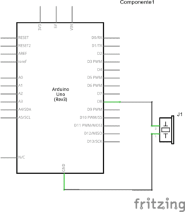
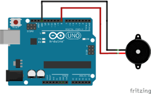
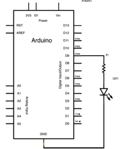
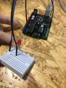
the first two circuits are easy to build. Just connect as the schematic suggests.

1

2

For the second circuits, we change the code in order to change the melody, it’s pretty fun!

The third one is quite difficult. We need to first read the schematic, not only to know how are the wires connected but also how the electricity flows between each component. The first time we upload the code, it doesn’t work. Later we found out that we forgot to ground one of the LEDs. The 10k ohm resistor is in parallel connection with the switch. and the 220 ohm resistor is in series connection with the LED. There’s another problem I encountered in the drawing of the schematic: no mater how I draw it, two of the wires always run across each other. With the help of Jingtian, I know how to draw the crossing but not connected wires.

Q1: I feel like I’m involved with technology anytime and anywhere. Even when I’m taking the piano courses, we use the electric piano to practice: every one plug in their headphones so that what they are playing can only be heard by themselves. It’s really convenient since there’s 8 people in our class, with the help of this technology, we can practice together and not disturbing others. This improve the efficiency of the class a lot. Also, I am sometimes consciously reducing my time of using phones. We are so used to phones. My definition of interaction: two or more agents response to each other through a medium. The two agents don’t have to be humans, they can also be machines. 

Q2: To protect the button from to much current.

Q3: I’ll make an LED carpet to put in my dorm that can change the brightness of light according to the environment.

Recitation 2: Arduino Basics – Lillie Yao

Introduction:

For this week’s recitation, I built 3 different types of circuits. The 3 circuits that I built were called Fade, toneMelody, and the Speed game. All three circuits operated differently.  By doing this recitation, I learned how to program a button game, turn on a LED light, and play music with an Arduino.

Materials:

1 * Arduino Uno
1 * USB A to B cable
1 * breadboard
1 * buzzer
2 * LEDs
2 * 220 ohm resistors
2 * 10K ohm resistors
2 * pushbuttons
A handful of jumper cables

2 * arcade buttons
1 * Multimeter (optional)

Circuit 1: Fade

In this activity, I connected the Arduino to the breadboard to power the LED light on the breadboard. This activity was very simple to complete and code. Although I did have some problems coding with Arduino, they were easily resolved after reading through the code.

Circuit 2: toneMelody

For this activity, we learned how to use Arduino and a speaker to play a certain series of sounds/tunes. This activity took me quite a while because I was confused as to which jumper cable should be connected to which sides and also connecting it to Arduino as well. Coding it was difficult because at first, it didn’t work and then we tried to incorporate the “pitches.h” file and we were also having trouble figuring that out, but we got it to work in the end!

Circuit 3: Speed Game

In this activity, I had to connect 2 LED lights that corresponded with the two buttons. The game was whichever player pressed the button 10 times, they would win and whoever won would have their light start blinking and the speaker would also go off and make a sound. Some difficulties I ran into was that the LED lights wouldn’t flash if one player won. Also, one of our buttons wouldn’t work, so the same one player would win each game. In the end, we just switched some wires and it worked.

Question 1:

The technology I use in my daily life does reflect the circuits that I made during this recitation. The first activity reminded me of the lights in my bedroom that I turn on and off. The second activity reminded me of a lullaby box that makes music when you play it. The third activity reminds me of just a normal two-player arcade game.

Question 2:

I’m not sure why we need to use a 10k resistor but I’ve always used it.

Question 3:

If I had 100,000 LEDs of any color, I would decorate my room with a bunch of lights that would have the ability to change colors and flicker whenever I want it to. I would just line up a bunch of lights alongside the wall or make a photo out of the lights on my wall into some sort of design.

Recitation 2: Arduino Basics by Isabel Brack

Overview

Overall, the circuits were interesting to test out as each got increasingly difficult. The first circuit, the fade, was the easiest and the last circuit was the most difficult because of the amount of connecting wires. We did not have time to finish connecting the fourth circuit. 

Circuit 1 Fade:

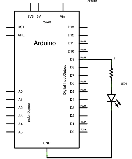
Fade Arduino Schematics

This circuit overall was not too difficult to complete. We connected the LED to ground and to the 220 Ohms resistor which connected to digital pin 9 (according to the code for fading). The light faded almost blinking repeatedly.

Video of working circuit:

Circuit 2 toneMelody:

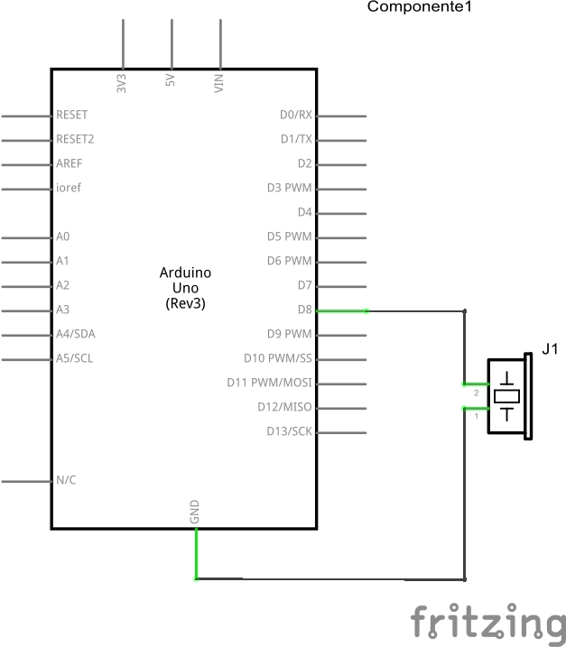
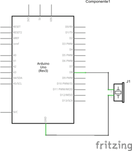
toneMelody Arduino Schematics

This circuit also was not too difficult and we did not run into any major issues. We connected the buzzer to digital pin 8 and ground. The speaker would play a preset melody.

Video of working Circuit:

Circuit 3 Speed game:

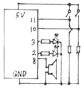
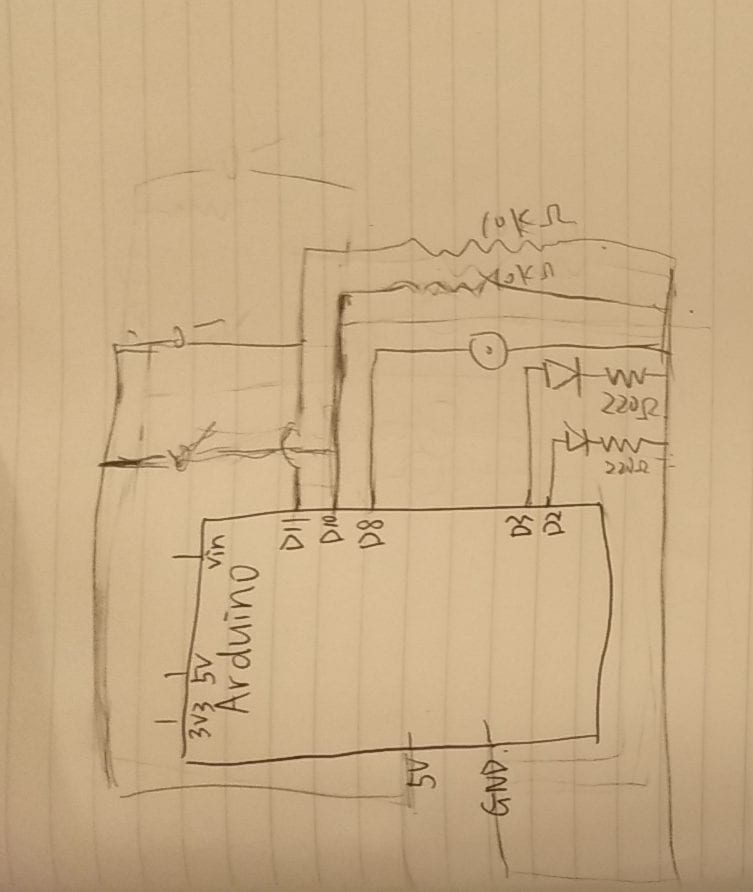
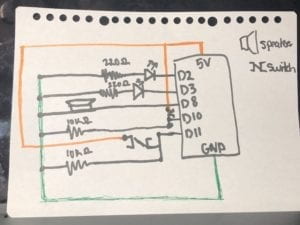
Speed game hand drawn schematics
This schematic is color coded for power (orange) and ground (green). The orange power even though it crosses over many wires only connects to the switches attached to pin 10 and 11.

This circuit was the most difficult only because there were so many wires connecting many components. If you missed a connection it was difficult to quickly find the wiring error because you had to check every single wire connection. We especially found issue with one arcade button as it was not soldered very well and its connection was a bit spotty. For this circuit we connected to 5 different pins, two connecting to the LEDs, two connecting to the buttons, and one connecting to the speaker. There were also two 10 Ohms resistors that are connected to the buttons and two 220 Ohms resistors that are connected to the LEDs.

Video of working circuit:

Questions

Question 1:

Between my personal understanding of interaction and the one I read in Physical Computing, I believe interaction is defined by an input, processing, and output. There are two actors in each interaction, and an input is provided, interpreted or understood, and then responded to with some sort of output based on the input provided. In the passage Physical Computing, interactions was given the analogy of listening(input), thinking(processing), and speaking (output). One actor listens to the other taking in the input, thinks about what they said and what the input means, interpreting how to respond, and then finally responds by speaking bact to them based on their cognition.

Question 2:

We used the 10K resistor to not overload the circuit. In addition, based on some external research of pull-up and pull-down resistors, according to “Pull-up/ Pull-down resistors- explained with calculations” and “Why use resistors with push button or switch with Arduino”, pull-up or pull-down resistors can be used to higher or lower resistance. With digital inputs like a switch turning it on or off (1s and 0s), without a resistor there is an inbetween section of voltage that is uncertain whether it would be assigned a 1/0 or on/off. This is due to noise or interference that surrounds us from other devices. The resistor closes the gap of uncertainty, pulling the voltage in this case down to ensure the switch is either on/off or 1/0.

Question 3:

If I had 100,000 LED lights and the coding and wiring experience to complete this, I would want to make a billboard-sized arcade-style pacman game that could be played in some public space by anyone. The lights at different brightness and colors would light up a for the most part non-changing background maze to play the game, and with a joystick like controller the player could control a small group of lights that would move (by blinking on and off) to show their packpam and another moving group of lights would be different monsters and or collectables for pacman. It would be pretty complex to upload the gaming code to the light board, but entertaining for not just the players also the public.