Recitation 5: Processing Basics By Yiwen Hu

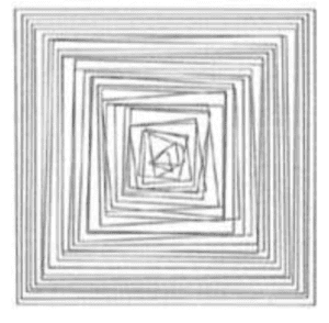
The image I choose is titled Computer rosace-series created by Vera Molnar in 1974. I choose this picture because I like the combination of irregularities and regularity. The shapes inside are triangles and squares with random size, with one embedding in another. The interesting thing is that while those shapes inside seem to be not following a certain order, they all revolve around the center and somehow looks symmetry. The symmetry becomes more apparent as the shapes extend outwards. It seems to me that this picture is implying that everything will finally be in order, even though they look messy at first sight.

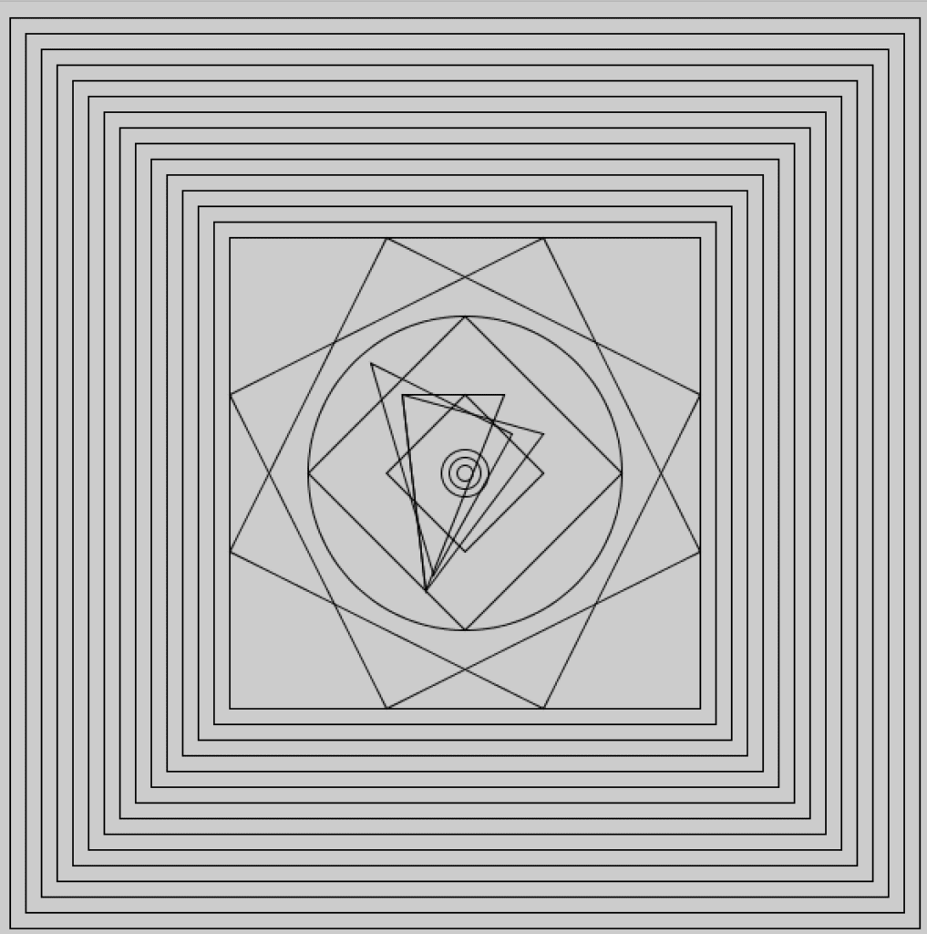
Based on such interpretation, I decide to create one image that has some shapes without explicit order in the center. The outer the shapes, the more regular they will be. Ultimately the shapes will be regular squares that revolve around the circle with steadily increasing size. However, to imply the underlying regularity of those seemingly irregular shapes, I would draw circles in the center as well as some regular shapes that interweave with those irregular triangles. Besides triangles and squares, I also add some circles to add diversity and enhance visual effects. The final result are as follows.

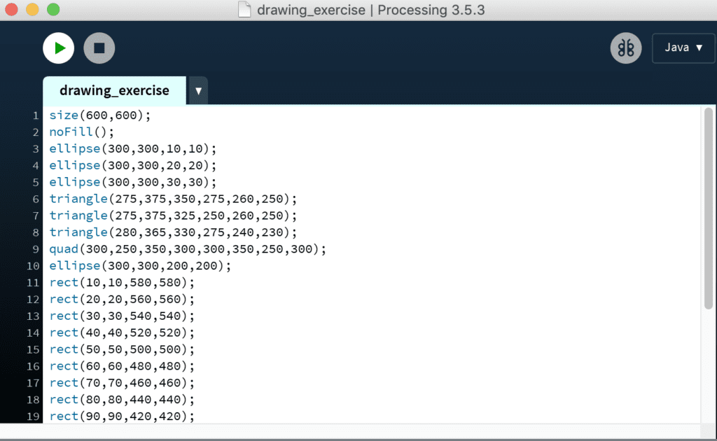
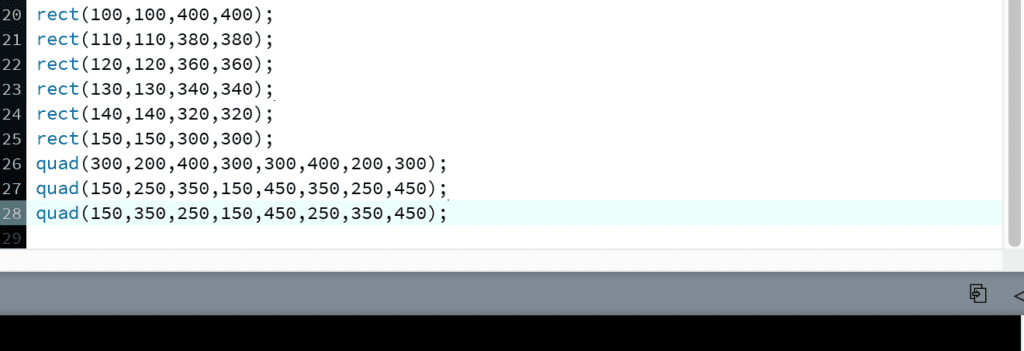
I started by drawing circles in the center as an anchor to create all other shapes that revolved around them. Then I drew some triangles with random size but they somehow revolved around the center. In addition, the triangles were related in some way, whether they shared the same side or vertex, implying entanglement between them. As the shapes extend outwards, the triangles became more regular squares and circle. The outer two squares that had the same slope but with different direction is also played with the idea of symmetry and order. In terms of the method, I scratched on paper first to calculate the exact coordinates of each vertex. I followed the principle that each vertex divided the line it touched into 1:2 ratio and then did calculation based on the canvas. My coding is as follows.

I really like Processing in terms of its ability to create ordered and exact shapes, which would be difficult for human hands to achieve. Order and symmetry is closely related to numbers, especially in coding. Therefore, I can create regular shapes such as the increasingly bigger squares that extend to the edges simply by incrementing the same numbers. 

Reference

Computer rosace-series by Vera Molnar. http://dada.compart-bremen.de/item/artwork/626

Recitation 5 Blog Post by Christina Bowllan

Step 1: Choose an image to be your motif

Josef Albers, Concealing, December 1940. Oil on Masonite, 27 7/8 x 23 1/4 inches (70.8 x 59.1 cm)

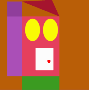
The picture I decided to recreate was Joseph Alber’s Concealing and I chose this one because, on the surface, it looks like a lot of shapes bunched together, but, to me, it looks like a house with a front lawn. Creating this image seemed like a fun challenge to try on Processing. 

Step 2: Draw your image in Processing

My initial goal was to recreate the exact image above, but in practice, things changed. Firstly, I created the purple and pink rectangles which look similar to  the original image. Creating this part of the motif proved to be more challenging than I expected because I had to figure out which numbers to plug into the syntax in order to place all of the shapes side by side. The colors of the motif and the original one also resemble one another, but I wanted to create my own version of Concealing— one that had a twist! On the one hand, the image looks like a house; I used the ellipse function to make windows and a version of the rectangle to make the doorknob. But, on the other hand, all parts of the motif resemble a face! The yellow ellipses are the eyes and the white door is a mouth. 

I think Processing has potential to realize the image well, but I have not figured out yet how to maximize all of the tools. It is interesting to think, though, that anything we see in the world can be broken down into a code for shapes and colors and, in turn, can create any visual in the world.

Code

//little rect
size(600,600);
background (185,94,7);
noStroke();
fill(144,62,155);
rect(50,10,100,100);

//side rect
fill(170,79,183);
rect(50,110,100,400);

//big rect
fill(229,63,93);
rect(150,110,250,400);

//top triangle
fill(165,20,47);
triangle(150,10,400,110,350,0);

fill(255,50,20);
triangle(150,10,400,100,400,100);

//white box on the inside
fill(252,252,252);
rect(240,320,120,150);

//doorknob
fill(255,0,0);
rect(320,400,20,20,3,6,12,18);

fill(249,250,5);
ellipse(220,200,100,150);
ellipse(340,200,100,150);

fill(59,155,33);
rect(150,510,250,400);

Recitation 5: Draw with Processing by ChangZhen from Inmi’s Session

I choose the logo of Sibelius because of its moderate difficulty. The original seems to be made up of primitive shapes, but carefully observing, we notice that they have different colors so we’ll draw them separately, and the clef has upper and lower layers so we’ll beware of the codes’ order.

  • Fill in spectrum with colorMode() and for(){}
  • Usage of bezier (starting point, control pt, ctrl pt, pending pt), curve doesn’t cross ctrl pt which instead pulls the curve toward itself.
  • Usage of arc where the angle is radian rotating clockwise from positive x axis.
  • Some colors vary 0~100, some 0~255, opacity 0~100. Lighter colors as bigger values.

Midterm Project by Barry Wang

Midterm Project – KAMEHAMEHA!

1. Preparation Stage: Ideas, Early Attempts and Failures

The most important point that the group project enlightens is the distinction between interactive and responsive. In my group project, the “Paint Your Day” machine is more like a responsive product. It is interactive only in the sense that the machine is making different choices according to different data that the sensor gives. The user only sees the output, which means that the user cannot directly feel the process of interactivity. The level of interactivity is not high enough. And we have analyzed several projects on the Internet, basically, those projects which we consider interesting involves human interaction strongly. For example, we looked at a mini arcade game machine.
One example game on it is the retro snake. The interactivity lies in the point that once the user moves the joystick, there is an immediate change on the direction the snake is going. By doing this, the user has a strong sense that I am controlling it, and it interacts with the user.

So the most important point that my partner and I would like to address is to create something that the user can be easily and strongly involved in. By that time, the class has just finished the content about controlling a motor fan, and we consider the motor fan might be a good point to start off since the output can be directly seen and heard.  

We started from the simplest point, trying to reproduce a remote control fan, and then add some extra features in it. We thought about putting an auto-mode in it, which is to adjust the fan speed according to the surrounding temperature. But we had never thought that this simple idea is such difficult to implement. We spent a whole night trying to figure out the difference between a TIP 122 and TIP 127 transistor since there wasn’t any TIP 122 transistor in stock and spent another afternoon trying to make the IR Receiver working properly. But the plan ended up because the IR Receiver keeps transmitting wrong data due to electronic noises that we cannot cancel even if we applied RC filter.

Besides the mechanical problem, we still do consider this product is too boring. So we ditched the whole plan and started to do more research. In the next stage of research, we looked at more interesting projects and reflected on the in-class projects. We reflected the mini arcade machine and the speed competition game in class and discovered that the most interesting and interactive way to create a project is to gamify it. 

At this point, Joseph came up with an idea of another speed game. It uses a distance sensor and a motor fan. The machine detects hand moving speed using a distance sensor, and the faster you move your hand, the stronger the wind will be. We then tried to gamify the project by setting up barriers and rewards. We consider that the speed of the fan is not direct, or visual enough. Thus we decided we make the fan to blow away something. The easiest way is by setting a paper cup wall. In this way, we have a complete gamified interaction. We have the user providing input data, Arduino mapping the moving speed to the rotation speed of the fan and the fan blows away cups as a gamified result.

This is a product that can be played by anyone, and the result is straightforward. The intention of this project is to make the user feel that they are applying a magical, invisible power to those cups. The users can feel a strong sense of achievement through the process of destroying the cup wall. This interaction involves the user in strongly. Besides, we consider this sequence of movements is similar to the “KAMEKAMEHA” action in animation Dragonball. We therefore decided to theme this project as Dragonball cause we believe this will make our project easier to be comprehended and much more interesting for those who watched the animation before. With the idea set, we started to design and produce this product.

2. Designing 

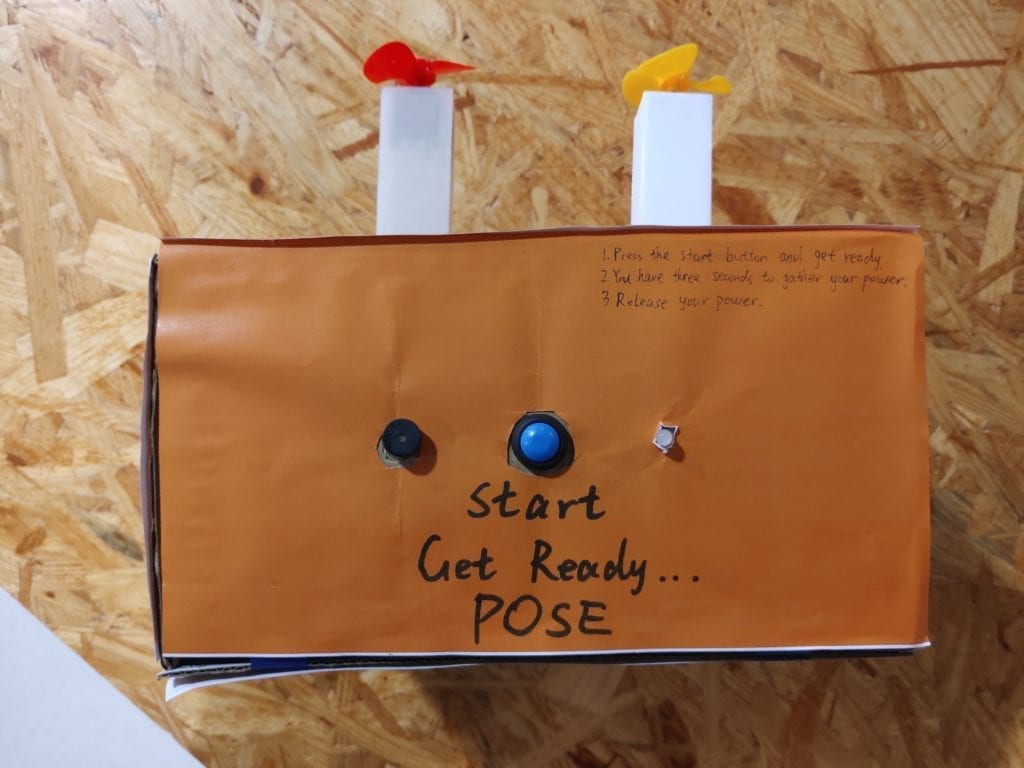
To maximize the user experience, we would like the machine to be placed in the middle of the user and the cup wall. The user pushes towards the machine, and the machine blows the cup away. This way, the user can feel that their energy is transformed in the air to the cup wall. We find a big cardboard box and decided the position of the distance sensor. (The reason we use a cardboard box is that it is easy to be modified, in case we improvise some features or some of the parts does not fit in properly. We do not need to laser cut a new one. It takes a long time and requires a small residual. )In our case, we put the sensor in the up-of-centre position, so that most of the users don’t have to bend down or reach up when doing the “KAMEHAMEHA” action. On the panel opposite, we would like to cut two slots to fit two motor fans. Using two fans can blow away more cups thus lead to a better visual effect.

Besides, since our output is a one-time output, we need to give the user a clear instruction on when to start. So we added a start button, a led and a buzzer to indicate the countdown and start command when playing.

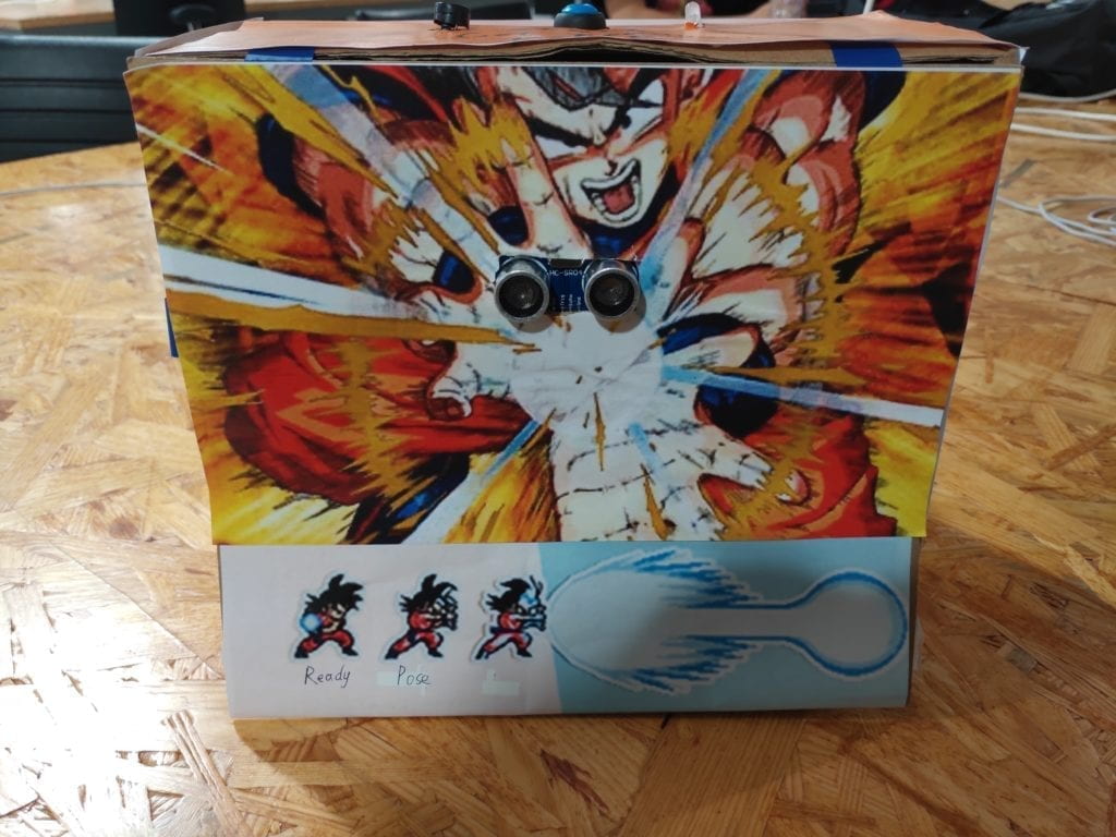
Also, we would like to decorate our project with the Dragonball themed elements. On the surface which we put sensors on, we used this picture and tried to make the sensor at the centre of Son-Goku’s energy ball. We would also want this picture as an implication of how the machine works. And on the two sides, we made two energy beam so that it looks the energy is sent from the user to the paper cups.


       Decoration on the panel that the user faces                                                          Decoration on the side panel

To provide instructions to the users who have no experience with the animation, we wrote a few lines on the top panel to illustrate how should the user interact with the machine. We consider putting them on the top panel would be the most efficient way since all the users will need to push a button to start. Then these sentences are less likely to be completely ignored. 
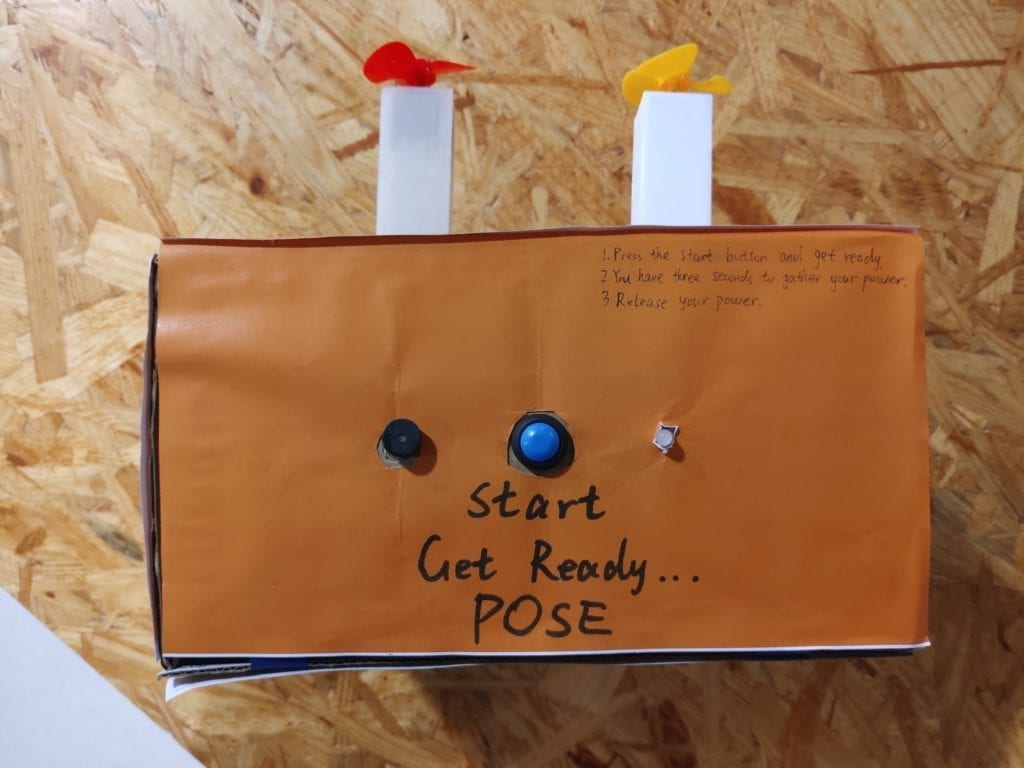
Instructions on the top panel

3. Fabrication & Production

Having learned and improved from the previous failures, the circuit building was no longer a difficulty for us. The whole circuit is functioning properly outside the cardboard. For the software part, we discovered that some times the signal from the distance sensor is nor correct, especially when the users put their hands very close to the sensor or the user is too far from the sensor. We optimized our code so that most of the correct movements can be detected. But there are still some accidental circumstances that the readings from the sensor are not correct. More testing and optimization can be made if we had more development time.

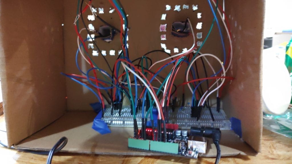
However, when we put all the components into the box, the problem comes. We put the circuit into the box and fixed the two motor fans on the front panel. And here is the test video:

In the design part, we neglected a huge factor, that is the airflow of the fan. Since we put the fan too close to the box, there simply was not enough air to blow the cups. On the contrary, since the air wasn’t flowing fast enough, the air pressure is pushing the cups in the opposite way. This was a huge setback to us since at this point, we didn’t have to much time, only about 1 day to the user test session.

To sort this problem out, we drilled some holes on the panel, but that did not help much either. The fans are still unable to blow away the cups.
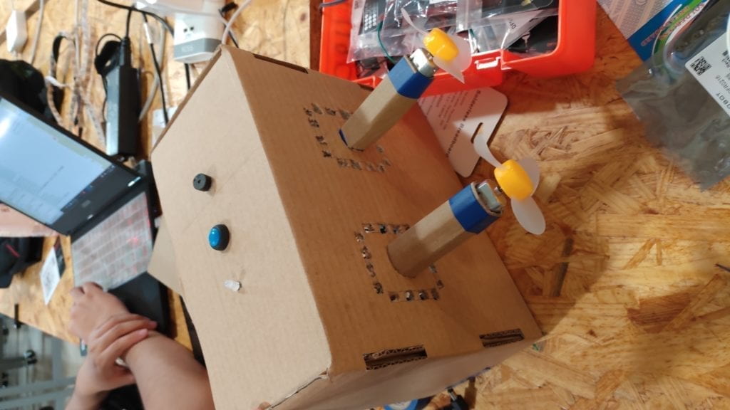
Then we decided to use two pillars to hold the motors and mount the pillar to the front panel so that the pillar can stick out to provide more air to the fan. But we did not have enough time to print 3D models before user test, so we used two cardboard pillars instead. Finally, the fans are producing enough airflow.
– User Test Session

The mechanism of the project worked well in the user test session, with only a few times that the machine didn’t work although the user did the correct movement. However, the biggest problem is that some users still can not play with this machine without our explanation. We overestimated the scale of the animation viewers, and we realized that we need to put more easy-understood instructions on it.

One of the user test cases:

– Further Improvements

First of all, is a better instruction system. We realized the fact that nobody is taking time to read anything like an operation manual. And it is difficult to describe a sequence of movements using words only. On this point, we decided to apply visual instructions. We found a picture that exactly shows the sequence of movements. And we put this picture on the panel that the user faces. In this way, they have a visual reference while preparing the movement. 
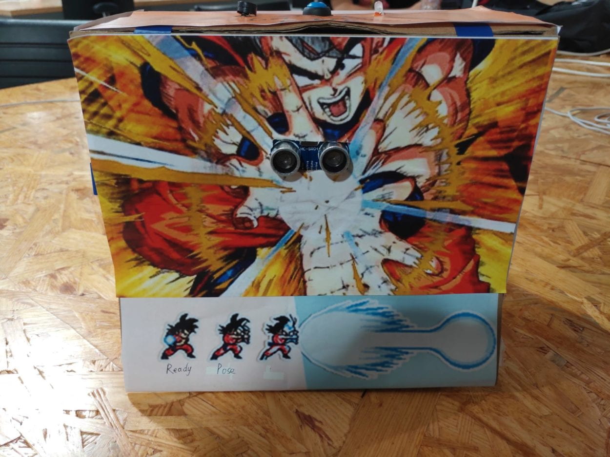
Secondly, we would like to substitute the two cardboard pillars with 3D printed models. They are tougher and more beautiful to look. While in the 3D printing process, I would say that it went far beyond my expectation. We built up a model using tinkercad and firstly tried to print them on the 3D printers in the 826 Studio. A compelling situation is that, somehow, while printing, one corner of the bottom surface will rise up, causing the whole model to distort.

Then we tried to print using the printers in the FABLAB. The first model we built was not big enough that the motors didn’t fit in because of the thickness of the 3D printing material. When printing the second model that we modified, another accident happened. Somehow the printing material tangled together and material roll got stuck. It affected the movement of the printer head and thus ruined the whole model.

Having changed the materials, we started our third attempt and printed two models using two separate printers together. One of them had a problem with the distance between the printer head and the tray. The distance was too close so that print materials got stuck together. We tried to initialize the printer, which didn’t help. Finally, we had to manually adjust the bias of z-axis of the printer head to move it further away from the tray. After all, we managed to get both printers working properly.

And here are the printed pillars:
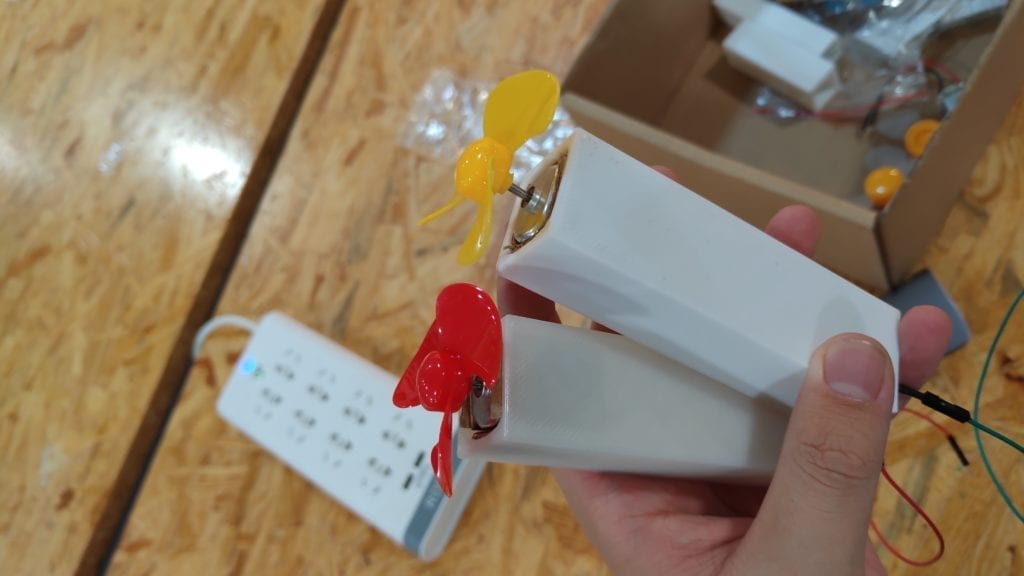
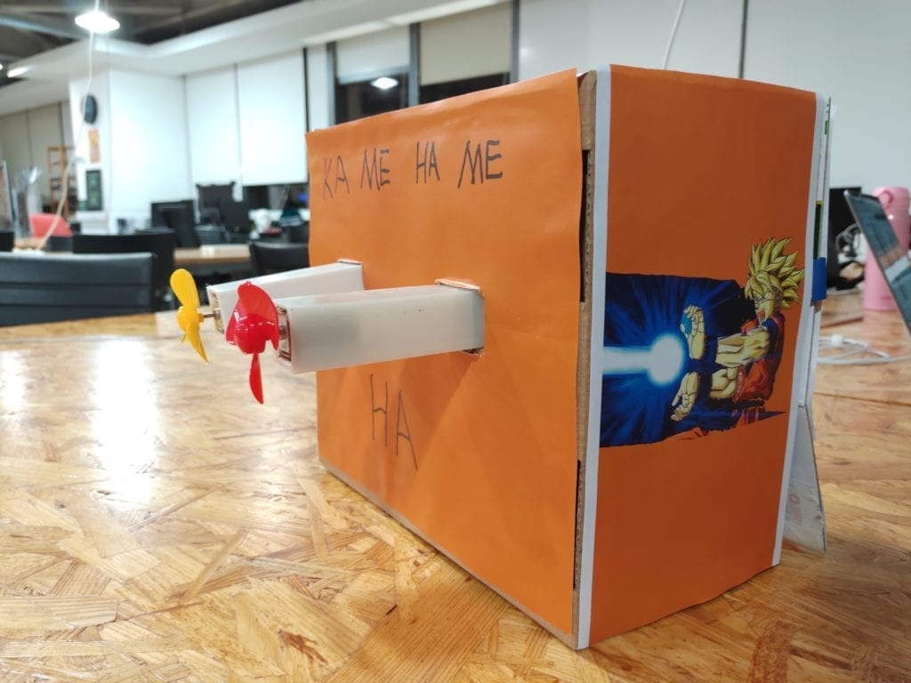
Up to this point, the main body of our project has been all set. The remaining was just some decorations. We redesigned a better side panel picture,  stuck our new instruction picture on and wrapped the whole product using orange coloured paper. This marked the end of our production phase. Here is what it finally ended up look like.
  

4.Conclusion

Our goal was to create a gamified interactive product. I think we have done a satisfactory job. We have successfully formed interactions using this product. The users are strongly involved in. In the final presentation, though there were some users who did not look at any instructions at all, overall, the result was good. The users were competing with each other to see who can blow away more cups. I think this is an interesting and highly interactive product. If we had more time, we would build another machine which blows in the opposite way, so that two users can compete with each other at the same time. Also, we would add a speaker to it to enhance the sense of participation. Moreover, we would work harder on the instruction system so that it is easy-understood and obvious enough.

Looking back on what we succeeded and failed to do, I would say that the most important thing is to start off as a user. Only in this way will we be able to create something that the users really like. During our research phase, we all like an interactive game or other cool stuff, then why do we create an automatic fan for the users in the first place? It is interactive but boring. What we need to keep in mind is that product is always oriented at users.

As a product that is centred at game and animation, this product brings a real sense of the movements in the animation into life to the users who have previous experience with the animation before. This product can be furtherly made into a toy for the kids. As a kid, who does not want some cool stuff? Who does not want to make the clips in the animation come true? This product is bringing absolute joy and interactivity with animation to these users. Bringing joy to the users is definitely the best praise to a product, and one of the ultimate goal of interactivity itself. 
project2: Merry Christmas music box –Katie – Inmi

how our project works:

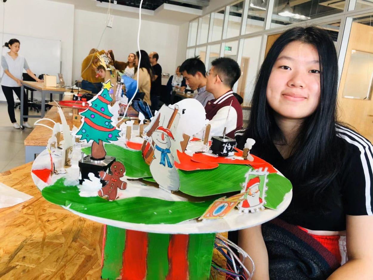
our final product:

Context and significance:

In my previous research about interaction, inspired by the definition of interaction given by Crawford (“a cyclic process in which two actors alternately listen, think, and speak” (1)), I define interaction as a kind of conversation where two or more actors are involved. They listen (receive the information), think (process the information) and speak (give out the processed information). There is one project that both shaped my definition of actors and let me rethink the process of “thinking”. The project is two computers play rock paper scissors together. In this case, the interaction has no human involvement but only two machines. But I see almost no cyclic process within the project: each computer runs its own random algorithm, choosing one of the three possible items. So, as we were designing our project, we kept in mind how can we enhance the process of “thinking” between two or more actors.

This summer I took a course called creative learning design. In that course we mainly focused on designing children’s music learning experience which has a very big market and lots of needs. So, I decided to make a project targeted to children and the goal is to in some extent help them be interested in learning music. That’s the starting point and we decided to think about how to enhance the music box experience of kids. In that course, one thing I remembered most is that children need instant response to their action, or they will lose interests sooner or later. The first thing we were going to design is of course the instant response to children’s action (for example, our first thought was to design several buttons and you press different buttons different songs will come out). But back to my research, we are not only making a responsive project but an interactive one. So, we are thinking about how children can “think” after receiving this response from our project, and how they react to the feedback they received which then forms a circle of the clinic process of interaction.   There are many kinds of music box and the most common kind is the one that you wind up the spring and the music will come out itself.

CONCEPTION AND DESIGN:

The action of “winding up the spring” gets the feedback of “hearing music” but it’s not interactive enough. Inspired by the winding up spring movement, I came to the idea of what if you turn the knob one step and one note will come out? the rhythm of the music is totally controlled by users. The user received the response from the music box and depending on the response one receives, he/she will then decide what to do next.

FABRICATION AND PRODUCTION:

Me and my partner cooperate very well. I took the responsibility of making the turning knob works, laser cutting the box as well as decoration. My partner took the responsibility of the two step motors and the potentiometers to control them. So, I will write some steps that I think is really challenging and important in this documentation.

Hook up the rotary encoder:

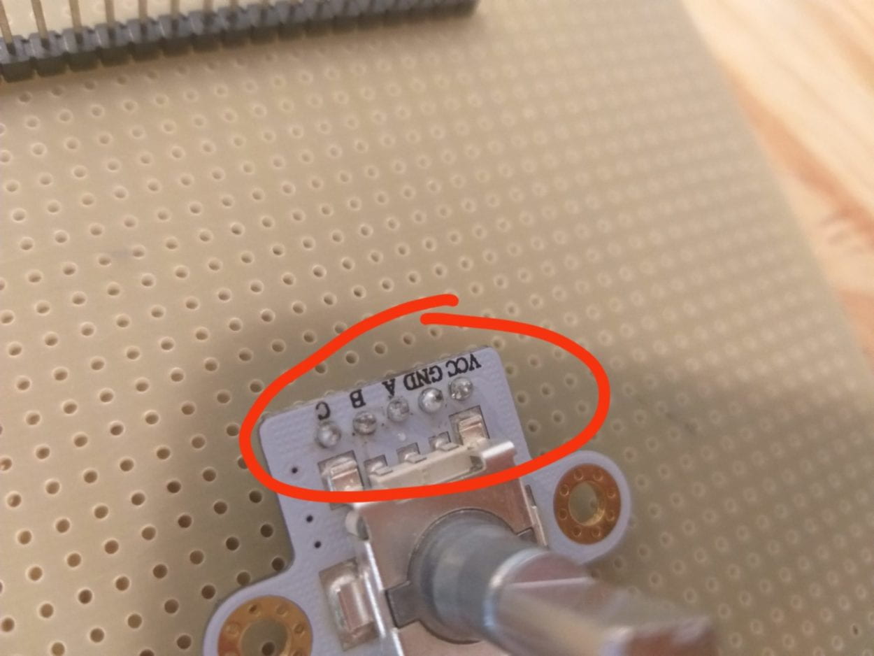
The first step and the most significant step is to find out and hook up the right component that can achieve my goal: easy to turn. The potentiometer is not the ideal one, so I search online and found one called Rotary Encoder. Our equipment room have this kind of rotary encoder but not the exact same type as the one I found on YouTube. The biggest challenge I think for me is to hook up the Rotary Encoder. The type in our equipment room is called “df robot ec11 rotary encoder”. So, I searched it on google and wanted to find out the tutorial of how this works. But I did not find tutorial of how to hook up this, the only useful information I found was “The module has three signal terminals: terminals A & B are encoder output; terminal C is the button signal output.” (from the official df robot website https://www.dfrobot.com/product-1611.html ). But I found a YouTube video of  how the similar rotary encoder works ( https://howtomechatronics.com/tutorials/arduino/rotary-encoder-works-use-arduino/). The names of the pins are different between the two: the one I got have five pins called: VCC, GND, A, B, C and the one I found online have the five pins called: CLK, DT, SW, +, GND. I then did some further research about the difference and hooked it up according to the YouTube video. (I forgot to take a picture of the wires L). I then hooked up the buzzer with the help of one of our recitation notes.  

Problems I faced when writing the code:

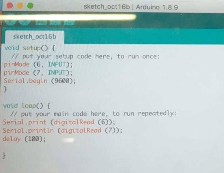
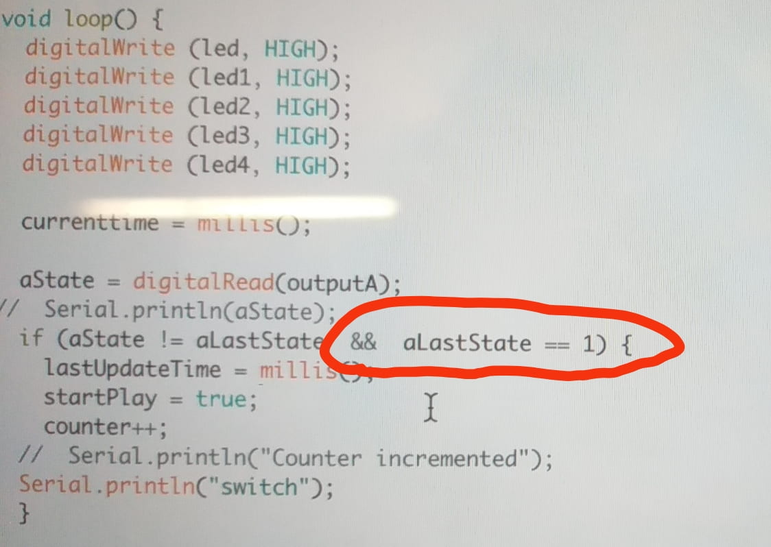
The next thing is the code, as we have done one making notes exercise in the recitation, it’s not that difficult compared to hooking up the encoder. In writing this code we need to define the output A and B first. I think the most important part is to define the two state (the current state of the encoder and the latest state. If the two states are not equal, then play notes. So, I will not explain in detail but only to note some problems I encounters. The first problem is that the rotary encoder kind of works after I uploaded the code: the music sometimes goes when I turned, sometimes there’s no music when I turned and sometimes there’s music even if I am not turning it. I asked for help from Dave, he thinks there’s no problem with my code and the wires. So, he writes a println to only show the output of the encoder from serial monitor. It turns out that the value is not stable and changing itself without turning. So, he thinks is the connection problem of the encoder. By asking Tristan, I decided to solder it. After soldering it, it was totally worked by our movement of turning the knobs.  But then another problem occurs, it always plays two notes in one turn. Tristan suggested me to start a new Arduino document (see the picture below) to only monitor the encoder. It seems to work very well because both the output A and B changes between 0 to 1 when I turn. I told him I’m going to double the notes in my code to solve the problem. But he suggests me not to do that but really think about how this algorithm works. I have no idea at that moment, but he suddenly knows what goes wrong: in each turn, the output changes from 0 to 1 then back to 0. In this case, every single turn makes the state of the output changes twice. In order to solve this, we add another statement in the if statement. (see the picture below).

soldering.

the new Arduino document to monitor the output of the encoder

the new document to monitor the output of the encoder

add a statement: only if the last state equal to 1, the note will come out.

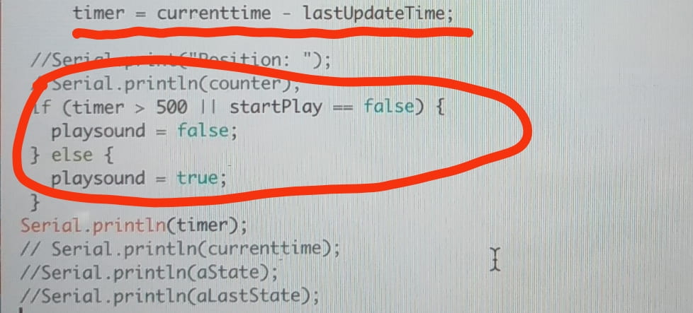
And there’s also some small problems like how to make the music loop: adding note count. How to make the note stop playing when there’s no turning in more than 5 seconds: adding a timer (millis). How to make the note only start playing when someone turns it first rather than giving out sound as soon as it’s hood up to the computer: add a boolin. Jingtian really helps me a lot in these small problems. She writes down the structure of those code on a sheet of paper to let me figure it out first. If I have some problems, she will explain very patiently to me.

how the timer works.

Our biggest improvement comes from Inmi’s user test. She told us the users would just randomly turn the knob. We first came up with the solution that to write down an instruction but Inmi suggested that this is the last choice if we could not come up with a better one. She also said that she would made it a big plane to turn which is more difficult and involves more body movements. From that point, we started to rethink about our design and then directly led to the final product.

For the laser cutting process, we cut twice. The first time I used cardboard to test the size whole of the whole since the size can be changed by hand if we use cardboard.

Conclusion:

I think our final project align well with our definition of interaction the two actors (user and the music box) listen (receive the information: the music box listen to the instruction which is the turning of the knob and the user, and the user listen to the notes the music box made), think (process the information: after hearing the notes, the user decided what to act next to respond to the notes, different speed in turning results in different rhythm of the song ) and speak (give out the processed information: the action of the user then results in another action of the music box). In this way, the circle of interaction has completed.

For the audience, I think they act the way we expect: they turn a few notes and later figured out the melody and then enjoy the changing of rhythm by turning in different speed (they could not go crazily fast since the plane is quite big and we add a lot of weight on the plane so it’s not so easy to turn. One response we got is that a user said he gets the since of control of the melody which makes him very happy because he never manages to play an instrument. For some users who only turns in one direction, it makes me think of the long play CD player where you can see the CD is turning all the time while the music is playing. Some other users turn it in both ways which 

Improvement: The first thing is that we haven’t figured out is that as there are two step motors turning along with the big plate, the wires connecting the two motors get mass up when turning. So, we might come up with a solution to solve this if we have more time. Second, instead of randomly stick our decorations on to the plate, we could make three or four different scenes so that it might be more surprising when users are turning the plate. Also, if possible, we could allow the users to control the movement of the characters on the plate.

Learn from setbacks: when the rotary encoder doesn’t work very well, I almost want to change it to the potentiometer we’ve used in class and one learning assistant even asked me, why don’t you use the potentiometer? But I stick to the rotary encoder (part of the reason is that is takes me a long time to hook it up) and try to solve the problem. What I learn from this is whenever encounter a failure, try to define the problem and solve it first rather than to run away from it and bring up plan B (which is not as ideal as plan A).

Our project provides an interesting and playful way that kids can interact with music. Since the demands for cultivate children’s interests in music is really large and many parents really worried about this, our projects in some extent help solve part of the problem.