Vivien Hao–Recitation 5

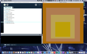
I chose this image because of its tone. The theme color for this image is yellow. It goes from brownish yellow to dimmed pink, then goes to dimmed yellow, finally to bright yellow. I see a transformational stage from this image. It looks like a depiction of a psychological changes that someone can have.

I wanted to draw an image that looks exactly like the original image. I made attempts to add the same textures onto my drawing. However, processing does not offer that function. So I had to stick to the plain texture. At first, I had to upload the image to a color depiction website. That website could figure out the color codes for me. Even though the codes that website gave to me did not match the original color codes exactly, but those codes were pretty close to the original ones. After getting the color codes down, I started drawing the squares from outside to inside. I set the size for the biggest square. Then add color codes into the background. After that step, I added rectMode. And set that to center. I repeated this step for the other two squares with slight changes in the color codes. For the innermost square, I added strokeWeight in order to depict that bright yellow stroke the original image contained.

I think my final creation is more or less similar to the original image. The colors in my image were not exactly same as the original image. But they are pretty close to the original ones. I think one noticeable difference is that my image does not have a texture feeling that original image had. If I could add the texture, then the final creation would look more similar.

I think drawing in processing was a good means of my design. It helps me to practice my coding skills.

Midterm Project Reflection – Chase Me If You Can – ChangZhen – Inmi Lee – You Xu as Partner

  • CONTEXT AND SIGNIFICANCE

After our group project DogLar was remarked as a responsive instead of interactive one, I discussed with You my definition of interaction “interaction is the iterative progression of the action and reaction between two units, and we found out some of DogLar’s functions are actually interactive, like that a proper behavior of the dog makes the dispenser open to give food as reward, then, the dog gets to learn what’s right or wrong and continues to behave itself, and this learning reinforcement is kind of iterated action and reaction according to my definition. But why that still didn’t seem interactive was that it lacks instancy so it wasn’t a good interaciton. Compared with one peer work at midterm user testing afterwards, which similarly, was to press some key to win but with the winning condition untold to be discovered by player’s one try after another, our DogLar is more of a pet trainning function which is different because it takes more time. Then You and I agreed that our midterm work should be real-time.

We also agreed that a device that supports two or more players like a platform can turn the interactions between each player and the device to the interactions among players. According to this, the soccer ball is a device that makes possible the interactions between the ball carrier and any other one who’s trying to strive or defend in a game. Requirement is to create something useful or recreational, and we chose the latter. To make the recreational work playful, You and I decided on designing a two-player real-time game device.

We thought up a lot of elements for the device, like a clock hand as input knob, music harmony as output, and colorful lights as output. The inspiration for the proposal finally chosen came from my dream where I was chasing another me who has identical velocity to mine, so I’d never make it to catch up. Thus, You and I determined to make a car chasing game. A good situation to play that can be when someone invites friends over for a party and would like to break ice and add fun to the party.

  • CONCEPTION AND DESIGN
    • Game in General

Two players push their own button to accelerate their respective car where there’s some distance between each. A player wins when her car chases the opponent’s from behind.

    • Car

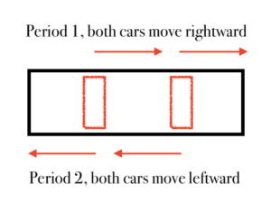
Shown in graph 1, the structure is DC motor and bodyshell. The bodyshell consists of two short cylinders. One has a hole that’s the same size as the motor shaft in the center. The other, observed from the circle face, is a loop whose open space lets the motor’s wires through. The two wheel cylinders are fixed together by two cylinder sticks at the diam-opposite side. The motor can be firmly attached into the hole due to friction force. The motor side of the bodyshell is on the track’s outer side. How the car works is basically the motor body hangs still and makes the shaft bring together the whole bodyshell to rotate and move forward.

    • Race Track

We had two options, loop or line, shown in graph 2 and 3.

As for loop, two cars are set at the diam-opposite side and will move in the same clock direction. Advantage is the track is infinitely long. Disadvantage is the circular motion can be too complex to have physical issues.

As for line, two cars are set at the second and third quartile position and move in the same orientation, and when a front car reaches end or after a certain amount of time, both head to the reverse so that they don’t move out of the track. A mortal problem with this scheme is that it’s not fair, because when they knock into each other, it isn’t the distance each covers that determines who successfully makes a chase. Imagine the car in the front strategically moves slow in one period to let the car behind catch up lots of distance and in the next period, the front car changes to the one behind and can easily catch up the little distance left.

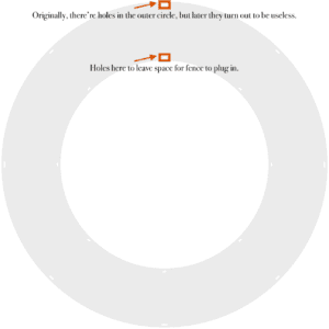
Thus, we chose to make loop. The track was made of wood by laser cutting, with the sketch drawn on Gravit, shown as graph 4. Later we added a decoration pattern onto the track on the laser cutting computer, shown in graph 5. The holes in the track lets fence to plug in. Two no-circle-face cylinder fences are vertically attached to the track’s inner and outer circle respectively.
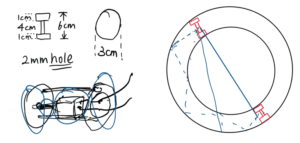
Graph 1                             Graph 2
Graph 3
Graph 4

Graph 5

Graph 6

  • BGM

We wanted to create background music to accompany the game. But we had difficulty multitasking an arduino. It seems a buzzer can only generate one central pitch at one time. We could’ve used two buzzers to create harmony, but it might be so complicated that it solely can be a midterm project. There are two songs for the two opponents. When one of them has pushed more times of the button, her character theme song rings repeatedly until the number of her push is surpassed. Originally, there was an alternative proposal to judge who’s at an advantage. We wanted to use distance sensor to detect if the cars are going to crash, and moreover, we even thought so far as to cling reflective papar on the outer fence’s inside to reflect the infrared to compute distance, shown in graph 2, the blue dashed lines. Later, we agreed that it wasn’t necessary to judge who’s at an advantage by their cars’ distance, rather, the difference of the times pushed works equivalently. Song one is equally long notes of C4, D4, F4, G4, A4, G4, F4, D4, and song two is similarly C4, DS4, F4, G4, AS4, G4, F4, DS4.

  • “Game Console”

Pushing button.

  • “CPU”

Bread board and arduino were placed in the track loop space, but in this way, wires easily winds kink. So we only puts a breadboard in that space and extends the wire outside the track to connect to arduino. Arduino is powered by computer, and car powered by 12v. Below is the code.

#include “pitches.h”

int step_1 = 0;

int step_2 = 0;

int swth_1 = 1;

int swth_2 = 1;

int preswth_1 = 1;

int preswth_2 = 1;

int distance = 0;

unsigned long toki;

unsigned long period = 0;

int thisNote = 0;

int melody[] = {

  NOTE_C4, NOTE_D4, NOTE_F4, NOTE_G4,

  NOTE_A4, NOTE_G4, NOTE_F4, NOTE_D4

  };

int noteDurations[] = {

  250, 250, 250, 250, 250, 250, 250, 250

};

int melody1[] = {

  NOTE_C4, NOTE_DS4, NOTE_F4, NOTE_GS4,

  NOTE_AS4, NOTE_GS4, NOTE_F4, NOTE_DS4

  };

int noteDurations1[] = {

  250, 250, 250, 250, 250, 250, 250, 250

};

void setup() {

  // put your setup code here, to run once:

pinMode(2, INPUT);

pinMode(7, INPUT);

pinMode(4, OUTPUT);

pinMode(8, OUTPUT);

pinMode(12, OUTPUT);

Serial.begin(9600);

}

void loop() {

  // put your main code here, to run repeatedly:

swth_1 = digitalRead(2);

swth_2 = digitalRead(7);

//Serial.println(swth_1);

if (swth_1 == 0 and preswth_1 != 0){

  digitalWrite(4, HIGH);

  delay(30);

  digitalWrite(4, LOW);

  step_1 += 1;};

if (swth_2 == 0 and preswth_2 != 0){

  digitalWrite(8, HIGH);

  delay(30);

  digitalWrite(8, LOW);

  step_2 += 1;};

preswth_1 = swth_1;

preswth_2 = swth_2;

  toki = millis ();

  if (toki % 2000 == 0) {

    distance = step_1 – step_2;

  }

  if (distance < 0) {

    if (toki – period > 250) {

      tone(12, melody[thisNote], noteDurations[thisNote]);

      thisNote ++;

      //Serial.println(thisNote);

      period = toki;

      if (thisNote == 8) {thisNote = 0;}

    }

  }

  else {

    if (toki – period > 250) {

      tone(12, melody1[thisNote], noteDurations1[thisNote]);

      thisNote ++;

      Serial.println(thisNote);

      period = toki;

      if (thisNote == 8) {thisNote = 0;}

  }

  }

  }

pitches.h

#define NOTE_C4  257

#define NOTE_CS4 272

#define NOTE_D4  288

#define NOTE_DS4 305

#define NOTE_E4  324

#define NOTE_F4  343

#define NOTE_FS4 363

#define NOTE_G4  385

#define NOTE_GS4 408

#define NOTE_A4  432

#define NOTE_AS4 458

#define NOTE_B4  485

#define NOTE_C5  514

  • FABRICATION AND PRODUCTION

Laser Cutting

Here I list the modifications after us really embarking on fabrication or receiving feedback in the user testing session.

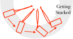
We got the car stand vertical. The car was likely to stuck onto the inner fence if it’s set like an ordinary car, shown in graph 6. It’s inevitable since the physics behind the self rotation and rotation around the loop track is lousy.

We reinforced the inner fence with thicker paper and gel tape and removed the outer fence. After putting cars vertical, we found that the car just contacts the inner fence to be provided with central force. The thicker paper provides better support, and the gel tape grabs the car from moving off.

We attached the button to a board paper after peer feedbacks the bad hand feel.

We didn’t take the advice of ringing the buzzer to acclaim who wins since who wins is obviously who chases from behind, and a buzzer won’t be able to speak like an audio.

We could have avoided use delay() in the code, or it’s unfair when one presses button in the delay opponent’s last press gives rise to.

We used millis() to multitask the music without disturbing the car moving.

  • CONCLUSIONS

Interaction is not limited between the user and the device. A device can serve as a platform for multiple players to interact.
recitation5: processing basics–Katie

The image I choose is the one from Mondrian:

this is a very famous abstract painting and I’m pretty impressed by how the three primary colors and the very simple rectangles can convey the power of shapes and color. Also, I found it pretty suitable to mimic by  processing: first, all the colors are plane, there’s no textures in those fills. Second, the shapes are really simple: rectangles. When we were asked to mimic a picture  by processing, this one immediately come to my mind.

step one: measure and choose 

I just eyeball it and set up the canvas as 800×800. At first I thought that no matter how big or small we set the canvas to be, we can always rescale it by our mouse. But as I started drawing, I found out that as long as you set a value to the canvas size, it is fixed and could not be changed. So then I adjust the canvas size to fit my screen: 650×650.

step two: colors

I use a online color picker https://imagecolorpicker.com/to grab the RGB values of the blue, red and yellow.

step three: functions

Then I use rectangle functions to draw is piece because compared to lines, it’s  easier to fill in with colors with rectangles. I also modify the stroke weight using strokeWeight function and fill the shapes with colors using fill. One thing to notice is that there’s no stroke on the border of the canvas, so for the (x,y) position, I set them into negative value.

this is my final work and the code:

Recitation 5 Processing Basics by Barry Wang

Recitation 5 Processing Basics

In this week, we were trying to use Processing to imitate a picture by applying some basic coding technique we learned in the last week.

Step 1: Choosing a Picture

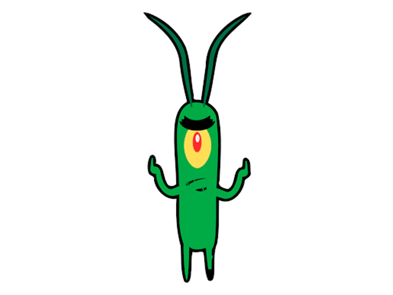
Since the line and shapes that we learned in Processing are some pretty simple models like rectangle, ellipse, line… I decided I would like to imitate something simple, like cartoon pictures or some simple art. Having searched through the Internet, one cartoon character popped into my mind, that is, Plankton from a famous cartoon Spongebob Squarepants. This is the picture that I selected.

I chose this picture because the body of Plankton is made up of several simple parts. An ellipse-shaped body, thick lines as hands, feet and antennas and also ellipse-shaped eyes. In Processing, my goal is to draw a basic but recognizable picture. 

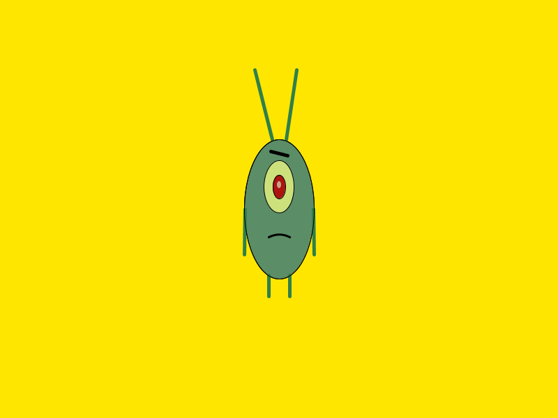
Finished Picture:

What needs to be improved further is the body of Plankton. Its body is not a regular-shaped ellipse. It looks more likely to be a rectangle and two semicircles at the top and the bottom. Also, the arms and hands could be improved in a more detailed way, which is to add curves and turns into it.

Code:

//canvas
size(800,600);
background(255,230,0);
// Body
stroke(0,0,0);
fill(91,141,103);
ellipse(400,300,100,200);
// Eye Brow
stroke(0);
strokeWeight(5);
line(388,217,412,223);
// Eye Layer 1
stroke(0,0,0);
strokeWeight(1);
fill(204,225,124);
ellipse(400,268,43,75);
// Eye Layer 2 
stroke(0);
fill(172,20,15);
ellipse(400,268,18,34);
// Eye Layer 3
noStroke();
fill(200,162,141);
ellipse(400,265,6,10);
// Antenna
stroke(47,128,72);
strokeWeight(5);
line(390,200,365,100);
stroke(47,128,72);
strokeWeight(5);
line(410,200,425,100);
// Mouth
//stroke(0);
//strokeWeight(3);
//line(385,340,415,340);
// Mouth_Curve
stroke(0);
strokeWeight(3);
noFill();
bezier(385,340,395,335,405,335,415,340);
// Feet
stroke(47,128,72);
strokeWeight(5);
line(415,395,415,425);
stroke(47,128,72);
strokeWeight(5);
line(385,395,385,425);
// Hands
stroke(47,128,72);
strokeWeight(5);
line(351,300,350,365);
line(449,300,450,365);
// Body Line
strokeWeight(1);
stroke(0,0,0);
noFill();
ellipse(400,300,100,200);

Overall, I consider drawing in Processing an interesting way to draw since I am drawing through codes, which I had never done before. However, I do think that Processing should more be put in creating some abstract works, for example, Tya’s creation. It takes a lot of time to draw a real-life, objective picture. 

Recitation 5: Processing Basics by Ian (You Xu)

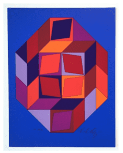
For this recitation, I chose an art piece. When I first saw this picture, the various colors are very eye-catching to me. The perfect symmetrical shaping and asymmetric color make this piece of the image a balanced art. I believe that by using Processing, I could perfectly represent the framework and details of this art. I also think choosing this one to work on would be very challenging since it has different shapes of patterns with all different colors. Therefore, for the purpose of challenging myself, I decided to emulate the original work as much as possible.

Original Work:

Original

Vasarely, Victor. Untitled #7 (blue, red and purple). http://www.artnet.com/artists/victor-vasarely/untitled-7-blue-red-and-purple-a-yqJv_4mtDacDa5WPyKeEZA2

Step 1: Measuring.

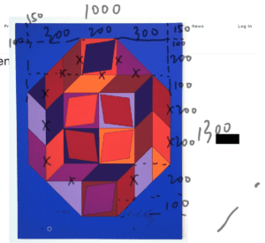
I started my work by measuring the original work. I export the website as a pdf document and measured the ratio of the length and the width of every shape as well as their exact position in the piece. I roughly labeled it on the pdf document. The screenshot of the file is attached below.

Measuring

Step 2: Color

Besides, I also need to figure out the color of each component. Therefore, I want to figure out the RGB of each color in the picture. I used an online website where I can directly get the RGB information by clicking the corresponding part of the image. However, since there are too many blocks of shape in the picture, it would be very time consuming and inefficient to match every one of them to a group of RGB data. Instead, I tried to categories them to certain colors. In Processing, I created variables with these color names and store the corresponding RGB data so that I do not need to refer back to the online website every time when I draw a new shape.

Step 3: Coding and Drawing

The remaining part is very straight forward since I had already had the precise data. In case to return back and check the code, I draw the image layer by layer and show it clearly in the coding part. One thing I found very interesting is that the sequence of the four corners to draw a quadrilateral is very important. It is like connecting multiple points with straight lines on paper. Following different sequences to connect them will result in different shapes.

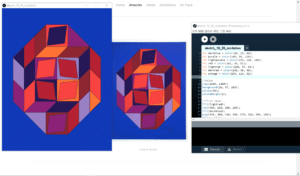
Processing Work

My work is in the left and the original work in the middle. Since the code is too long, I attached it to the link via Google Drive.

Reflection:

During this recitation, I learned much about the functions to draw certain shapes by practicing. I also understand better the concept of RGB. Comparing my work to the original work, the high similarity may demonstrate that it is a good way to use Processing to emulate this work. However, I believe I could do better if I can get inspired by the concept the art to create other art forms by computer that continue to inspire others.