Recitation 1: Electronics and Soldering (Madeline Shedd)

Recitation 1: Electronics and Soldering

February 15th, 2019

Partner: Henry S

Goal:

This weeks recitation focused on learning the basics of circuits and soldering by completing a few simple circuits based on a schematic.

Materials:

  • Breadboard: the base of the circuit, it allows for power to flow through a series of connections between different parts of a circuit
  • LM7805 Voltage Regulator: converts 12V to 5V, a voltage the buzzer can handle
  • Buzzer: outputs a sound when supplied with the correct amount of power
  • Push-Button Switch: opens and closes the circuit, lets electricity flow when wanted
  • Arcade Button: the same concept as the switch, depending on the user it allows electricity to flow when pushed down
  • 220-ohm Resistor: adjusts the resistance of the electricity so the correct amount of power flows through the circuit
  • LED: light-emitting diode, the “lamp” of this exercise
  • 100 nF (0.1uF) Capacitor: used to stabilize the flow of electricity by storing power while the circuit is connected to power and releases it once power is disconnected
  • 10K ohm Variable Resistor (Potentiometer): adjusts the amount of resistance so more or less voltage is let through
  • 12-volt power supply: provides power to the circuit
  • Barrel Jack: the connection that supplies the power
  • Assorted Jumper Cables: connects the components of the circuit together

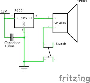
Circuit 1: Doorbell

Circuit 1 Diagram

Circuit 1

We didn’t have too much difficulty piecing everything together on this first circuit. Once we were able to understand the schematic, we thought we had everything in the correct place. But we were having problems making the buzzer make a sound. We rechecked connecting wires and moved the capacitor around and still no sound. We then decided to ask for a little help because we didn’t know what else could be wrong. After getting help, we exchanged the voltage regulator and still no sound, switched the buzzer and yet again got no sound. So we got another voltage regulator and tried one last time and the circuit worked perfectly.

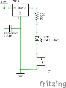
Circuit 2: Lamp

Circuit 2 Diagram
Circuit 2

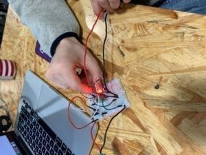
Creating the circuit for this one was much easier than the first one since we didn’t have to deal with faulty parts this time. We basically kept everything the same except for removing the buzzer and adding in the resistor and LED. After doing this, the light successfully turned on our first try.

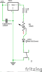
Circuit 3: Dimmable Lamp

Circuit 3 Diagram

Circuit 3

This circuit was also pretty easy as well. We at first mixed up the wire positions for the potentiometer, but after rechecking the schematic we were able to figure it out. We also added on the arcade button at this stage, it was a very simple exchange. Once everything was connected, the circuit worked as planned.

Question 1:

I do believe these circuits have some level of interactivity. We can see this because we have to interact with it, push a button or twist a potentiometer, and then getting a result from that interaction, the light turning on or a buzzer going off. But this interaction stops with this result. The text presents the definition, “interaction: a cyclic process in which two actors alternately listen, think, and speak”. The circuit listens to us by responding to our actions, but it’s not like the light will speak back to us or have some effect that prompts us to do something in return. Because of this, the circuits can be interacted with but to a low level of interactivity.

Question 2:

By combining interaction design and physical computing, you’re just opening a new door for self-expression another medium. Through this self-expression, you can connect with others who view your work. With interactive art, you can connect with your audience in a much more intimate way. In Zack Lieberman’s video, not only did he intrigue his audience greatly, the got up close and interacted with his work which probably left a bigger imprint on them rather than if they had just observed. With this extra ability to be able to convey more and to have your audience literally experience a piece of artwork is, in my opinion, more memorable and touching than simply just viewing a painting.

Caren Yim – Week 1 : Electronics and Soldering

Introduction: The purpose of this week’s lab was to understand the basics of circuits through the completion of three circuits and to learn how to solder.


Circuit 1: Doorbell

Components:

  • LM7805 Voltage Regulator: maintain a constant voltage level for the circuit
  • Breadboard: base that allows for circuit connections, usually used for prototyping stage 
  • Push button Switch: interrupts the flow of current going through the circuit which allows the speaker to turn off and on
  • Speaker: creates sound, in terms of the circuit it allowed us to know if our circuit was working
  • 100 nF Capacitor: stores electrical energy and allowed the LM7805 Voltage regulator to work
  • Wires: allow current to flow from one location to another
  • 12 Volt Power supply: supply power to the breadboard

Process: In Circuit 1, my partner and I had to familiarize ourselves with the symbols and their corresponding components. When we first started, we started by inserting the speaker on the breadboard and attempted to work around that. However, we were advised that to start, it would be best to insert the 12 volts and the ground first. This was helpful because it built our understanding of ground and volts. The first problem we encountered was when we placed the capacitor into the power bus and the ground bus. We were told that instead, we can attach it to the same row of the regulator since the rows were already connected to both the ground and 12 volts. In the end, we were successfully able to get the circuit working.


Circuit 2:  Lamp

Components:

  • LM7805 Voltage Regulator: maintain a constant voltage level for the circuit
  • Breadboard: base that allows for circuit connections
  • Push Button Switch: interrupts the flow of current going through the circuit which allows the speaker to turn off and on
  • LED: light emitting diode, emits light
  • 220-Ohm Resistor: prevent too much current from passing through to the LED, control current flow
  • Capacitor: stores electrical energy
  • Wires: allow current to flow from one location to another
  • 12 Volt Power supply: supply power to the breadboard

Process: The first step in this circuit was making sure the resistor was at 220 ohm, to do this we used a multimeter. Since half of the setup was identical to circuit 1’s setup, we only took out the parts that weren’t needed for the second circuit and worked from there. An error that was made in this process was not considering the polarity of the LED light. When we completed the schematic we were not sure why the LED wasn’t lighting up, we asked for guidance and were told it was because the polarity of the LED was inserted wrong. After fixing this, the LED light lit up when the switch was pressed. We were successful in creating circuit 2.


Circuit 3: Dimmable Lamp

Components:

  • LM7805 Voltage Regulator: maintain a constant voltage level for the circuit
  • Breadboard: base that allows for circuit connections
  • Push button Switch: interrupts the flow of current going through the circuit which allows the speaker to turn off and on
  • LED: light emitting diode, emits light
  • Resistor: prevent too much current from passing through to the LED, control current flow
  • Capacitor: stores electrical energy
  • Wires: allow current to flow from one location to another
  • 220-Ohm Resistor: prevent too much current from passing through to the LED, control current flow
  • 12 Volt Power supply: supply power to the breadboard
  • Variable Resistor: allows the current resistance to be adjusted

Process:  The materials needed for this circuit was almost identical to the second circuit except a variable resistor was added. This circuit was easy to build because only the variable resistor needed to be added. We were a little troubled at first due to not being able to figure out which part of the variable resistor corresponded with the ones in the diagram provided. However, we were able to figure it out and in the end, successfully completed the circuit.


Questions: 

1.  In the reading, the author defines interaction as “a cyclic process in which two actors alternately listen, think, and speak”. Based off of this definition the circuits that were built today showed a level of interactivity. This is because each component within each circuit in a sense was “listening” to the parts before them for instructions and then “thought” about its role and then by creating a reaction they “spoke”. This process is repeated once an individual gives the circuit the signal to start. Even the process of building circuits was interactive, we inputted the work and as a result, the circuits responded back to us by having the LED light up or even the speaker making a sound when the switch was pressed. These were all responses to an action and that is what interactivity is.

2. Interaction Design and Physical Computing can be used to create interactive art in many ways. An example of the lengths both these combined can do to contribute to the interactive art realm is a project inspired by Tony Quan, a paralyzed graffiti artist. By studying human behavior and combining that with computing it allowed for the production of interactive art. The eye-tracking art was able to move in conjunction with a part of the human body. Interactive art gives life to a new form of creativity and has endless possibilities.

Documentation on soldering and electronics


The recitation last week mainly focuses on a number of basic electronic operations, soldering and configuring some circuits.

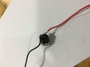
The process of soldering is pretty simple. After heating up the soldering iron, put the solder at the tip of the iron to let it melt, before putting the iron on the joint. After the spot is also heated up, apply solder onto somewhere near the joint and wait for it to melt. When the work is done, clean the tip. Though I have played around with it before, it seems my procedures were totally wrong. When I was soldering, I have been skipping the step on tinning the tip. What’s more, I have also been applying the solder right onto the joint or even the soldering tip. But finally, my partner and I have got the wires soldered securely soldered to the button. We even soldered to jump wires together.

The button soldered to wires
Two wires soldered together

Building the circuit was not complicated. Though when building the first circuit, we have encountered difficulties in reading the diagram, as the capacitator was a bit annoying. Therefore, we were confused about which socket should the wires and switches be connecting to. Another problem was the direction of the switches. We weren’t able to control the on and off of light using the switch, because we weren’t clear of the direction of the switch. After checking the information about the direction in the button, we made it work. But afterwards, we were able to get the first and second circuits working pretty quickly. The third circuit, however, involves more electrical components, so we were a little hesitated in wiring up. And my partner was not very familiar with the breadboard so that he almost connected two pins of an electronic component to the same row of the breadboard. After correcting his tiny mistake, we got our last circuit working as well. During the rest of the time, we used the potentiometer to make the tone of the speaker change while turning the potentiometer.

The brief description for the electronic components involved are down below:

BreakBoard: the board that has built-in wires, through which different electronic components can be connected more easily 

Voltage Regulator: adjust the voltage flowing into the circuit

Speaker: a buzzer that can make noisy sounds

Push-Button switch: used to turn the circuit on and off

Arcade Button: works the same as the Push-Button switch, but there are less pins to connect

Capacitor: store electricity inside, which would feed back to the circuit

Resistor: to reduce the current in the circuit and prevent the components from burning out

LED: light up when connected in a circuit

Variable Resistor: a resistor that can change its ohms

12 volts power supply: the power for all components in the circuit

In general, technically speaking, the recitation last week wasn’t very complicated. The difficulties we encountered mostly resulted from our lacking dexterity.

Based on The Art of Interactivity, our circuits have very limited interactivity. The only possible interaction was pushing the switch and have the light lights up or the speaker makes a sound. It is almost in the same circumstances as opening the door of the fridge when the light in the fridge lights up, or a person avoids the branches falling from a tree.

When it comes to the relationship between physical computing and interactive design, physical computing acts as the empowerment of the interactive design idea in the artists’ mind. And in the process, the physical computing itself is only a tool and should be made accessible, in order to have the artist focus on creating completely.

IMA Week One- Nate Hecimovich

Partner: Dominick Nardone

Circuit 1: Doorbell 

To make this circuit we followed the instructions using a button, a speaker, a voltage regulator, and a capacitor.  When constructing this circuit we ran into an initial problem, we had the voltage regulator going horizontal across the breadboard instead of vertically. 

We had the voltage regulator turned in the wrong direction restricting the flow of electricity making it impossible to complete the circuit.

However, once we figured out the problem with the voltage regulator we quickly corrected the issue and our doorbell worked.

Circuit Two: Lamp

We had a much easier time with this circuit now that we had figured out the voltage regulator situation.  However, for this project we included a resistor to prevent the LED from frying.  Based off of the knowledge acquired on the first project this one came very easily. 

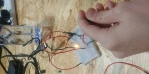
(Apologies for the terrible quality of this photograph)

Circuit 3: Dimmable Lamp

This circuit was made by replacing the voltage resistor with a variable resistor allowing us to make the light more intense and also dimmer by turning the knob.  (Photo not available for this part)

Circuit 4: Arcade Button Lamp

This one was simple as we just replaced the basic button for this arcade button soldered onto two wires.  By removing the button for the arcade button it made it way more fun and interactive.

Questions:

Our circuits were interactive in the fact that we were communicating with it and it was communicating back to us by either working or not working.  By listening to the circuit we were able to make corrections and eventually arrive at the final solution in which it would listen to us flawlessly.  Through communication on both ends as stressed in the reading we created “interactivity”

By combining the concepts of interactive design and physical computing we as a species can tackle problems that used to be unsolvable.  This opens up new frontiers of exploration, and also opportunistic to help people in all walks of life.  One example that was demonstrated this perfectly was the play station device created by NYU students for the severely disabled adolescent which allowed him to play baseball games without physically having to do the movements necessary to do it the conventional way.  There are so many doors that are opened up by the combination of both of these concepts whether it be just for fun and games or actual, meaningful societal contributions.

Recitation 1:Electronics and Soldering(Alex Wang)

Week 1 Recitation is on basic circuits and soldering. We are tasked with the construction of three different circuits, door bell, lamp, dimmable lamp and replacing one of the buttons with an arcade button.(Schematics below)

Process:

The overall process went very smooth, even when both me and my partner had minimal experience in hardware. The circuit wasn’t functioning properly a few times during our construction(mostly loose connection on the breadboard) but we were able to track down the problem by using the sound function on the multimeter fairly easily.

Videos of all working circuits, including arcade button modification

:

Reflection:

I think this recitation was a very good way of getting us started with electronics. I was a bit confused at first, but with the provided schematics and the reference pictures I was able to figure everything out fairly easily. To be able to make something that works feels very satisfying and fun.

Documentation Questions:

Q1:After reading The Art of Interactive Design, in what way do you think that the circuits you built today include interactivity? Please explain your answer.

I understand interactivity as giving a wanted feedback when given certain action, just like the input and outputs of a circuit or program. As for the circuits we have built in this weeks recitation, we interact with the electronics by pressing on a button or turning on a knob, and in response the electronics would give back a beep or a flash for us to know its functioning.

Q2:How can Interaction Design and Physical Computing be used to create Interactive Art? You can reference Zack Lieberman’s video or any other artist that you know.

My personal interpretation of how art is different from other things is how it has meaning behind it, or the ability to give people certain feelings. And implementation of interactivity with the use of sensors can enable the user to experience art through an medium that gives more interaction to the whole body as opposed to just watching a movie or listening to a song.