Recitation 2: Building Circuits by Lana Henrich

Recitation Week 2: Building Circuits

Circuit 1 – Fade

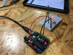
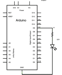
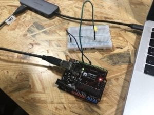
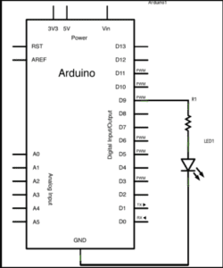
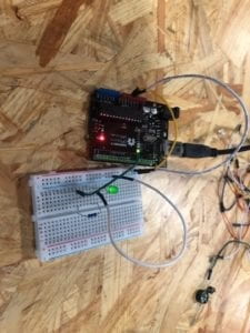
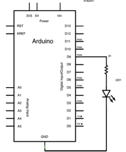
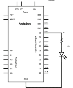
Building this first circuit went very smoothly for us, as we built similar circuits in the first week’s Recitation. Looking at the diagram, we connected the necessary cables to the breadboard and the LED, and were able to quickly finish building the circuit. Following this, we loaded the code onto the Arduino program, and the circuit worked properly. Compared to last week’s circuits, building this one was a lot easier for us, as we were very comfortable with the materials and knew right away what we had to do to get started.
Circuit 2 – toneMelody

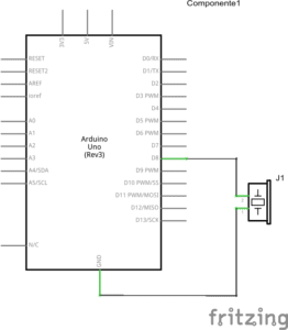
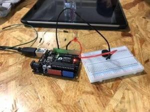
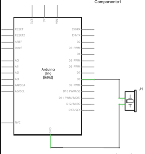
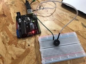
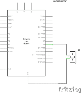
Building this circuit was also relatively easy for us, as we had worked with a buzzer before in the previous recitation, and the code was already written out for us on Arduino. This circuit required only 2 jumper cables, and so we were able to finish building quickly and upload the code.
Circuit 3 – Speed Game

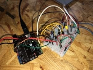
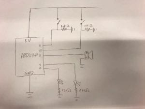
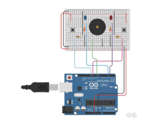
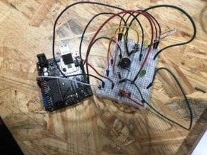
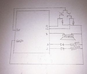
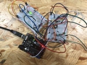
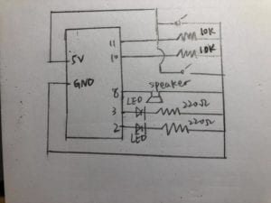
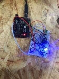
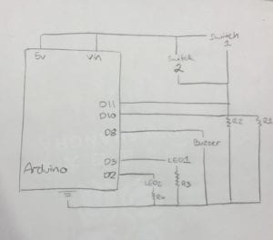
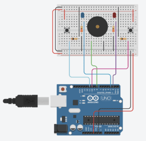
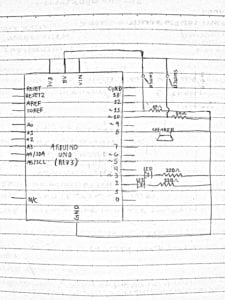
Building this last circuit took us a lot longer than building the other two, as this circuit required many different jumper cables, and multiple resistors, buttons, and LEDs. It was a bit hard for us to read the diagram, as the labels of the ports were written very small and a lot of cables required connection from different points around and to the breadboard and Arduino board. Although it took us a while to correctly place all the cables and keep tracking of everything we already put into the circuit, we were nevertheless able to get the circuit working on the first try. It was actually very fun to play the game which we uploaded onto the Arduino, as all parts worked smoothly every time we played. Drawing the diagram after building a circuit was also a bit of a challenge, as there are so many connecting parts and points vital to the circuit. This was the most challenging circuit we had gotten so far, and though it looked intimidating at first, it proved to be easier than expected, though it was a bit time-consuming.
Question 1

Interaction is the communication between humans and technology, wherein people trigger certain responses from technological devices through specific actions. For example, when someone uses a smart phone, they can touch (interact with) with the screen in order to cause a certain response, such as the opening of an application.

Question 2

The inputs I recognized were the buttons, the arcade buttons, and resistors. The outputs I recognized were the speaker and LED lights.

Question 3

If I had 100,000 LED’s, I would create a wall display on which the LED’s can light up at different times and in different colors in order to create moving images and patterns (such as a wave crashing down or a silhouette of a person walking). This display could go in an art museum, and have a tablet set up where people can select the images they want to be created by the lights.

Question 4

By image I.1 in the Physical Computing reading, I can understand that interaction with technology is limited to what part of the computer we can physically interact with. A computer can only “see” the parts of us we use to interact with it, such as our fingers (to type). Even technological devices like muscle sensors are limited to only what parts of ourselves we connect to the device. Further advanced technologies, such as eye trackers, also have specific algorithms and codes that they follow which allow them to work; meaning our interactions with them are limited to what the devices have been pre-programmed to do. While humans have the ability to form and perform infinite thoughts and actions, technology can only do what it is taught, and cannot think for itself.
INTM-SHU 101 (006) – Week 2: Arduino Basics – Caren Yim

Introduction: The purpose of this lab was to understand the basics of Arduino. This was done through the completion of four circuit projects.


Components:

1- Arduino Uno  
1- USB A to B Cable
1- Breadboard
1- Buzzer
2- LEDs
2- 220 ohm Resistors
2- 10k ohm Resistors
2- pushbuttons
Handful of Jumper cables


Circuit 1: Fade

Having been provided the schematic for this circuit we didn’t run into any problems. We were aware that the wires connected to the Arduino needed to match the programming for it. We also knew that we had to make sure the polarity of the LED was inserted correctly. Thus, when we ran the circuit, the LED was fading, we had successfully completed the task.


Circuit 2:  toneMelody

As with the first circuit, we were given the schematics, therefore, the task was not hard. We were able to successfully build the circuit and the speaker did emit the melody it was supposed to.


Circuit 3: Speed Game

 Circuit 3 schematic

This circuit was really challenging for my partner and I. We were not provided the schematic and instead had to follow the circuit diagram. This was a little challenging to read because of the abundance of wires in the diagram. At points during the progress of building it was hard to keep track of which wires were connected to one another. When we thought we had finished building the circuit we tried running it, but the Arduino was not turning on. The instructor came by to see what was happening and figured out that we had created a short circuit. And that was why it was not working the way we intended it to. We had connected too many wires and voltage was running through where it was not supposed to. The instructor helped us fix the problem and the game finally worked. In the future, I would be more cautious about where I am placing wires and read the diagram more carefully.


Circuit 4: Four Player Speed Game

For this circuit, we paired up with another group. As a group, we changed the wires so that the two breadboards were connected to one another. Afterward, an instructor came by and guided us in altering the code, we changed the brackets within the code and the four player game was working.


Questions

1. Technology in this day and age is inescapable. It is hard to even imagine a world without technology. Everything that we do is aided by the use of technology in some way shape or form. From completing an assignment to purchasing items, every day the use of technology is present. In the circuits that we built, it gave me a better understanding of the behind the scenes of the devices we interact with every day. Technology has been simplified towards its consumers causing us to not really realize the complexity of it and how different parts interact with one another behind the screen.

Building the circuits and running code through it gave me a better understanding of how there needs to be an input (code) that goes into the microcontroller and the microcontroller then processes the information and then outputs the instruction. As reflected in the text “Physical Computing” this process is what the root of interaction is; parts working together to complete a given task.

2.  If I had 100,000 LEDs of any brightness and color at my disposal I would make an art piece. I think using LEDs to create a portrait of someone would be pretty amazing. By programming specific LEDs to turn off and on at a given moment would allow the LEDs to take a different form. Using LEDs as a medium for art is also turning technology into an art form. I would want my work of art to be placed in a museum.

INTM-SHU 101 – 005 Week 2 Documentation by Sam Li

Circuit 1: Fade

Fade LED Circuit
Fade LED Circuit
Fade LED Circuit

Process:

  • First, we put the LED light and the 220 ohm resistor on the breadboard. We also connected the shorter leg of the LED to the ground through a wire on the breadboard.
  • Second, we used another wire to connect the ground rail on the breadboard to the ground pin on arduino board. We also used a wire to connect the button 5V pin to the breadboard, serving as a powersource.
  • Then, we found the “fade” code from examples, connected the arduino board to my laptop, checked if we’ve chosen the right right port and board. We uploaded the “fade” code.

Result and learning:

  • Result: The LED was originally on when we connected it to the 5V power source. When we uploaded the code to arduino, after a while, the LED started to fade regularly.

Circuit 2: toneMelody

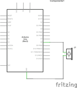
Schematics for toneMelody
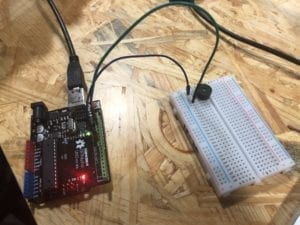
toneMelody Circuit
toneMelody Circuit

Process:

  • First, we put the buzzer on the breadboard.
  • Second, we used a wire to connect the positive end of buzzer to upper pin 8, and a wire to connect the negative end of buzzer to upper pin ground.
  • Third, we connected the arduino board to my laptop, uploaded the “toneMelody” example code

Result and learning:

  • Result: the buzzer started to create its melody sound after uploading the code, as seen in the video below

Circuit 3: Speed Game

Speed Game Schematics
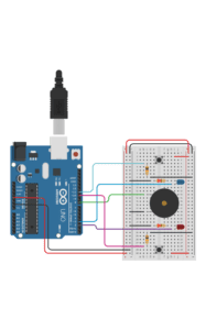
Speed Game Diagram
Serial Monitor when playing the game

Process:

  • First, we placed two switches on the breadboard, respectively connected to two 10k ohm resistors.
  • We placed two LED lights, respectively connected to two 220 ohm resistors through the breadboard.
  • We placed a buzzer at the center of the breadboard
  • Then, we used wires to connect the arduino 5V power source pin to the breadboard and another wire connecting breadboard to the bottom ground pin, and connecting the positive rails on two sides.
  • We used wire to connect pin 11 and pin 10 respectively to the two switches,  and used two wires to connect the 10k resistors to the ground.
  • We connected pin 3 and pin 2 respectively to the two LEDs, and then linking the two 220 ohm resistors to the ground, respectively.
  • Then, we connected the arduino board to the laptop, and uploading the speed game code.

Result and learning:

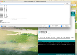
  • Result: We opened the serial monitor as we tested out the circuit. After we pressed the reset button, we saw on the serial board showing instruction about when to begin, by “Ready? Go”. My partner and I respectively pressed our buttons, as fast as we could. Eventually my partner won the game, with the LED lights turning on, the buzzer creating a melody, and the serial monitor showing both how many times we each pressed and the result of the game.
  • Learning: I learned from professors that the 220 ohm resistor is connected to the LED to prevent the LED from breaking; the 10K ohm resistor is connected to the switch to give out signal. I also learned that the serial monitor allows us to check and monitor the interactive process. If any parts of the circuits goes wrong and we are not able to see from the appearance of the circuit, we can probably use the serial monitor to find out which part goes wrong.

Question 1:

Reflect how you use technology in your daily life and on the circuits you just built. Use the text Physical Computing and your own observations to define interaction.

The Physical Computing text argues that physical computing creates an interaction and dialogue between the physical and virtual world. Similar as what’s stated in the article about interactivity, the authors of the Physical Computing text argues that interaction is an iterative process that involves listening, thinking, and listening of two actors. The interaction between human and computer involves how humans give out signals (inputs), how computers listen and think (processing), and how computer speak out with computational outputs.

In my everyday life, my interaction with my laptop is the most salient example of human-computer interaction. When I press certain keys on my laptop, my computer receives my inputs, it thinks about/processes what information I gives out, and then it speaks with media output such as letters showing up on my computer screen.

The circuit of fade LED light we built on the second recitation also involves such an interaction. As I upload the arduino code to my arduino board, the device receives my message and listens; it thinks about what command or messages I have sent out, telling it to control the fading of a LED light. Then it speaks out with the output, which controls the LED to fade regularly.

Question 2:

If you have 100,000 LEDs of any brightness and color at your disposal, what would you make and where would you put it?

If I have 100,000 of such LEDs, I want to create a giant installation that creates interaction between human emotions and the LED lights. When an audience stands in front of the installation, their facial expression and body movements will be captured by sensors and video cameras. If sensors detect an audience to be in happy mood, the LED lights will light up in warm colors and configure the shape of a smiley face. If the the audience was sensed to be in a bad mood, the LEDs will change into cold colors and create the shape of a sad face.

I want to place this installation at an enclosed space but located at a busy area of the city center, for instance, the West Nanjing Road in Shanghai or Time Square in New York. I hope the installation will help people take a break from the bustle and hustle of everyday city life, and become more mindful of one’s inner emotional state.

Recitation 2: Arduino Basics by Qianyue Fan

Introduction: In this recitation, we explored how to understand the use of codes in the Arduino and built more complicated circuits.

Partner: Malika (Weiyi Wang)

Date: 22nd February

Materials:

1 * Arduino Uno

1 * USB A to B cable

1 * breadboard

1 * buzzer

2 * LEDs

2 * 220 ohm resistors

2 * 10K ohm resistors

2 * pushbuttons

2 * arcade buttons

A handful of jumper cables

1 * Multimeter (optional)

Circuit 1: Fade

Process: For the first circuit, we connected it quickly as the diagram shows and uploaded the code, and the LED flickered. It is worth noticing that we put different types resistors apart so that we would not mix them up. Also, the instructor reminded us not to connect Arduino board to power supply before completing the circuit.

Circuit 2: toneMelody

Process: Building this circuit was easier than the previous one. We connected the Arduino board, the breadboard and the speaker according to the diagram before connecting them to power supply. The speaker played a melody when we uploaded the code.

Circuit 3: Speed Game

We built the circuit following the instruction here. Although it was easy to connect the components one by one, we did not understand how it worked when doing so. However, we still made some experiments and discovered that it did not entirely work as the recitation instruction said. To be specific, regardless of time, whoever clicks the button ten times first wins.

(Optional) Circuit 4: Four-player Speed Game

Process: We had enough time to figure out how the optional circuit works. We only need to add another two-player circuit to our own and it required few adjustments, so we started from the code. Although neither of us knew how Arduino codes work, we tried our best looking at the logic in the source code. Since we both learned some Python before, it gradually became clear how the code was organized and what each part of the code was aimed at. Step by step, we copy each part of the code to add player 3 and 4. We guessed what some symbols mean and followed suit. In the end, an instructor helped correct our code which lacked a bracket. For the circuit, we found another group and simply connected their wires for power supply to our Arduino board, and it immediately worked when we uploaded the code.

Question 1:

Reflect how you use technology in your daily life and on the circuits you just built. Use the text Physical Computing and your own observations to define interaction.

Technology may refer to any of the skills used in the production of goods and services. Therefore, every moment I am enjoying the benefits that technology brings in daily life. From the bicycle invented centuries ago to modern microchips in the cell phone, technology is widely used to facilitate travelling, learning, entertainment and almost every aspect in my life. When building the circuit, I was mainly using modern information and electronic technology that enables the miniaturization of electronic equipment, making it possible for me to make interactive gadgets without much difficulty. Interaction is an interactive process of listening thinking and speaking between two or more actors, and we can also consider it as input, processing and output when interacting with computers. This is a two-way activity, where people and computer both receive information from the other and react.

Question 2:

If you have 100,000 LEDs of any brightness and color at your disposal, what would you make and where would you put it?

I would put all the LEDs on the walls and the ceiling of a small room to make it a work of art. By changing the input signals, the LEDs can mimic the scene of time and space travelling, create moving colors according to the chosen music, or simply give people a calm and warm feeling when meditating. It would be a perfect place to stimulate imagination and creativity, or to seek mental relaxation when feeling stressed.

Recitation 2: Arduino Basics by Shuyang Cai

Circuit 1: Fade

Schematic:

Photos:

Reflection:

As we have tried to build this circuit during the class, this task was quite easy. We successfully built it during the recitation without difficulty.

Circuit 2: toneMelody

Schematic

Photos:


Reflection:

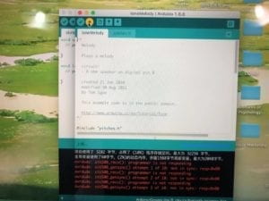
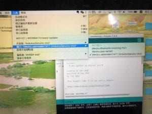
For circuit 2, the schematic is quite simple, but we had a problem when trying to upload the program in Arduino. It showed that the program is overdue and failed to upload the program. Finally, after the assistance of a teaching fellow, we realized that it was because we forgot to change to the correct port. Once we fixed this mistake, the circuit started working. According to this experience, we should always make sure to change to the board and the port before uploading the program.

Circuit 3: Speed Game

Schematic

Photos:


Reflection:

Compared to the previous two circuits which we built rather smoothly, this one is much harder. It took us some time to figure out how the electricity flows through the circuit and we made several mistakes during the process. Firstly, when we finished building the circuits and connect it to the computer, we found that the LEDs on the Arduino board did not light up, which indicates that we might have a short circuit. After checking the circuits, we found that we connected wires with the wrong leg of the switch. However, when we were testing the circuit, we found the LEDs on the Arduino board glittered as we push the button, which is another sign of short circuit. Therefore, we had to check the circuit again. It turned out that we have connected the wires to the wrong end of the resistor. After correcting the mistake, we tried to run the program for the third time, and luckily we succeed.

Question 1:

The use of technology in daily life and on the circuits are very important, for it is something that helps make our ideas true. Technology is an indispensable part of interaction because it enables us to control the interaction and make it do what we want. However, interaction should always be at the center of innovation. From my perspective, interaction means communication between human and machine. For example, people use their sense organs to either receive information from the machine or give instructions. And machines, in return, after inputting and process, output information that can be received by human sensory.

Question 2:

I will use them as streetlights and put them near roads and avenues. The LEDs might have different colors according to different weather or different time of the day. They can also be used to show the speed of the cars. For example, if cars exceed the speed limit, the LEDs will turn red. They might be used as early warnings as well. When there are cars coming from the opposite lane, the LED will glitter so as to warn drivers to pay attention.