Recitation 9: Media Controller——Leah Bian

For this week’s recitation, I created a Processing sketch to control the movement, size and color of an image. Data from Arduino are sent to Processing, which thus decides the image’s attributes. I used three potentiometers to adjust the analog values, and used the “serial communication” sample code as the basis for further modifications.

It was not hard to build the circuit, since we use potentiometers quite often. After finishing the circuit, I started to write the code. I adjusted the “Serial. print()” and “Serial. Println()” functions to send the data from Arduino to Processing smoothly. I chose an image from the famous cartoon “Rick and Morty” as my media. I decided to let the three potentiometers control the movement, size and color of the image respectively. I used the “map()” function to limit the analog values. It was not difficult to write the code for changing the image’s size and position, but changing colors was a bit complicated. I chose colorMode(RGB) to set the image with various colors, instead of only with white, grey and black. I used the “tint()” function to set the color. But since I only have one potentiometer controlling the color of the image, I can only set the image with analogous color schemes.
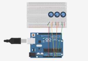
0
diagram

This is my code for Processing:

import processing.serial.*;

String myString = null;
Serial myPort;
PImage img;
int NUM_OF_VALUES = 3;   
int[] sensorValues;  

void setup() {
  size(800, 800);
  img = loadImage("rickk.png");
  setupSerial();
  colorMode(RGB);
}

void draw() {
  background(0);
  updateSerial();
  printArray(sensorValues);
  float a = map(sensorValues[0],0,1023,0,800);
  float b = map(sensorValues[1],0,1023,0,255);
  float c = map(sensorValues[2],0,1023,400,800);
  tint(b, 30, 255);
  image(img,a,200,c,c);
}

void setupSerial() {
  printArray(Serial.list());
  myPort = new Serial(this, Serial.list()[5], 9600);
  myPort.clear();
  myString = myPort.readStringUntil( 10 ); 
  myString = null;
  sensorValues = new int[NUM_OF_VALUES];
}

void updateSerial() {
  while (myPort.available() > 0) {
    myString = myPort.readStringUntil( 10 ); 
    if (myString != null) {
      String[] serialInArray = split(trim(myString), ",");
      if (serialInArray.length == NUM_OF_VALUES) {
        for (int i=0; i<serialInArray.length; i++) {
          sensorValues[i] = int(serialInArray[i]);
        }
      }
    }
  }
}

This is my code for Arduino:

void setup() {
Serial.begin(9600);
}

void loop() {
int sensor1 = analogRead(A0);
int sensor2 = analogRead(A1);
int sensor3 = analogRead(A2);
Serial.print(sensor1);
Serial.print(“,”);
Serial.print(sensor2);
Serial.print(“,”);
Serial.print(sensor3);
Serial.println ();
delay(100);
}

Reflection:

This week’s reading, Computer Vision for Artists and Designers, inspired me a lot. According to the article, Myron Krueger, the creator of Videoplace, firmly believed that the entire human body should have a role in people’s interactions with computers. In my previous definition of an interactive experience, I also mention this idea. Videoplace, an installation that captured the movement of the user, makes my hypothesis concrete and clear. In the project that I made for this recitation, the user can interact with the device only with the potentiometers, which makes the interactivity here quite low. Besides, the whole process is too simple and it does not convey any meaning implications, compared with the other art works mentioned in the reading, such as LimboTimeand Suicide Box. In conclusion, an interactive experience should let the user fully engaged, probably by physical interaction and building up a meaningful theme. The project that I made this time is not highly interactive due to various limitations, but I will try to create a satisfying interactive experience for the final project.

Reference:

Computer Vision for Artists and Designers: 

https://drive.google.com/file/d/1NpAO6atCGHfNgBcXrtkCrbLnzkg2aw48/view
Recitation 9: Media Controller

Intro

This purpose of this recitation was to further connect Processing and Arduino.  This time we used media as the bridge between them, in hopes that we can use this knowledge to help with our final projects. 

Processing Code

import processing.serial.*;

String myString = null;
Serial myPort;

int NUM_OF_VALUES = 3; /** YOU MUST CHANGE THIS ACCORDING TO YOUR PROJECT **/
int[] sensorValues; /** this array stores values from Arduino **/
PImage photo;

void setup() {
size(500, 500);
background(0);
setupSerial();
img = loadImage(“IMG_5849.JPG”)
rectMode(CENTER);
}

void draw() {
updateSerial();
printArray(sensorValues);

fill(sensorValue[0]);
rect(width/2, height/2, width/2, height/2);
 map(sensorValue[0], 0, 1023, 0, 255);
if (sensorValue[0]>= 0) {
tint(0, 0, 255, 150);
}

}

void setupSerial() {
printArray(Serial.list());
myPort = new Serial(this, Serial.list()[67], 9600);
myPort.clear();
myString = myPort.readStringUntil( 10 ); // 10 = ‘\n’ Linefeed in ASCII
myString = null;

sensorValues = new int[NUM_OF_VALUES];
}

void updateSerial() {
while (myPort.available() > 0) {
myString = myPort.readStringUntil( 10 ); // 10 = ‘\n’ Linefeed in ASCII
if (myString != null) {
String[] serialInArray = split(trim(myString), “,”);
if (serialInArray.length == NUM_OF_VALUES) {
for (int i=0; i<serialInArray.length; i++) {
sensorValues[i] = int(serialInArray[i]);
}
}
}
}
}

Recitation09-clover

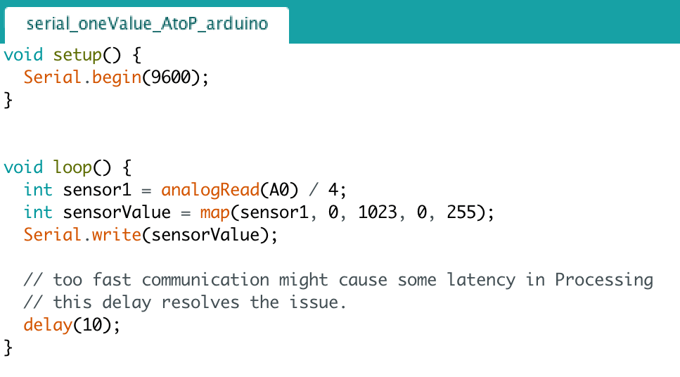
The code for the Arduino:

void setup() {
Serial.begin(9600);
}

void loop() {
int sensorValue = analogRead(A0) / 4;
Serial.write(sensorValue);

delay(10);
}

The code for processing:

import processing.serial.*;
import processing.video.*;

Movie myMovie;
Serial myPort;
int valueFromArduino;
void setup() {
  size(480, 480);
  background(0);
  printArray(Serial.list());
  myPort = new Serial(this, Serial.list()[ 1 ], 9600);
  myMovie = new Movie(this, "dancing.mp4");
  myMovie.play();
}
void draw() {
  if(myMovie.available()){
  myMovie.read();
}
  image(myMovie, 0, 0);

  while (myPort.available()>0) {
    valueFromArduino = myPort.read();
  }
  if (valueFromArduino >= 0 && valueFromArduino< 100) {
    filter(INVERT);
  } else if (valueFromArduino >= 110 && valueFromArduino< 180) {
    filter(POSTERIZE, 6);
  }
  println(valueFromArduino);
 // tint(255, 0, 0); 
}

recitation9(the video)

What I learned:

  1. To show the movie I need to put image(myMovie, 0, 0);  in front the code for the filter to show the movie.
  2. By setting dividing the value from Arduino into different rages, and setting in the filter, the potentiometer can control the color of every pixel to change the movie into different color while playing.

Reading Response:

When reading the article, I feel that Computer vision algorithms can catch some very detail changes of the human movement which greatly strengthens the interaction of the project. I was really impressed by the the Contact interaction, it provide my a diverse way(catch the orientation of a person’s gaze and the facial impression) of how can this technology actually be used in a project to make good interaction. Also the LimboTime game show how greatly Computer vision algorithms can affect the users’ interaction which make me think that I should think more about in what way can I use the technology I learn to make good interaction, I should stand from a user perspective when working. Also another point this article really impress me is the technology is more like a tool to support a good interaction. Just like the writer said the Videoplace was developed before Douglas Englebart’s mouse became the ubiquitous desktop device, the widespread technology is not the most important part contributes to a successful project. The technology is to make the communication between people easier and sometimes create a new way for people to know each other more. It make me think that the technology I used may not achieve the goal which is to interact with the users because the response I gave back to the user doesn’t make the communication continuous. The user may feel boring and don’t want to participate more. Next time, I should consider technology as a tool to strengthen the interaction but not to create fancy effect which is not that interactive.

Source: Levin, Golan. “Computer Vision for Artists and Designers: Pedagogic Tools and Techniques for Novice Programmers.” AI & Society, vol. 20, no. 4, 2006, pp. 462-482.

Recitation 9 Documentation

For recitation 9, we were to use Processing to manipulate a form of media, either an image or a video, with a physical controller corresponding with Arduino. Using the given code from the examples, we modified the code from the 01_oneValue_arduino_to_processing to correctly communicate the code from Arduino to Processing’s media output.

Using the functions pushMatrix() and popMatrix() from this week’s classes, I was able to make the image move and interact with the potentiometer from Arduino. These two functions allowed the image to be transformed, with pushMatrix() saving the current coordinate system to the stack, while popMatrix() restored the prior coordinate system. This allowed the image to jump from one place to another, in conjunction with the media processing from Arduino. 

Since I only used one potentiometer to control the input of the image, Arduino only reads one value to Processing. Ergo, I used the oneValue_arduino_to_processing example from our classes. I incorporated analog input via Arduino through the use of a potentiometer, then serially connected Arduino to Process to manipulate an image of my hamster. The potentiometer would adjust the image size by twisting it, reading the variables as an analog value and sending the input values as output values in Proccesing. 

Code for Processing:

import processing.serial.*;

Serial myPort;
int valueFromArduino;
PImage img1;
color mouseColor;
float mouseR, mouseG, mouseB;

void setup() {
  size(600, 600);
  img1 = loadImage("hamster.jpg");
  background(126, 137, 155);

printArray(Serial.list());

  myPort = new Serial(this, Serial.list()[3], 9600);
}


void draw() {
  while ( myPort.available() > 0) {
    valueFromArduino = myPort.read();
  }
  println(valueFromArduino);
  pushMatrix();
  translate(0, 0);  
  rotate(radians(map(valueFromArduino, 0, height, 0, 500)));
  
  image(img1, 100, 100, width/(valueFromArduino+1), height/(valueFromArduino+1));
  popMatrix();
  mouseColor = img1.get(mouseX, mouseY);
  mouseR = red(mouseColor);
  mouseG = green(mouseColor);
  mouseB = blue(mouseColor);
  println(mouseR+" "+mouseG+" "+mouseB);
  set(width/2, height/2,mouseColor);
}

Code for Arduino:

This week’s reading, Computer Vision for Artist and Designers, discussed the scope of applications that modern computer vision technologies has, especially in the field of military and law enforcement. But in recent years, an increase in the use of non-traditional computer programming applications such as Processing has contributed to the rise of a visual focus in the electronic arts and visual design communities. By using Processing, we are able to focus more upon the visual elements within coding, and therefore able to explore a multitude of technologies in order to execute such projects. Particularly in this recitation’s project, we used technology to serially connect images within physical hardware. Processing allows us to execute machine vision techniques within a digital environment, as it is extremely well­ suited to the electronic arts and visual design communities (Golan et al., 7). This application can be expanded into much more expansive projects that similarly connect media input and output, with these tools commonly seen “to create art installations, performances, commercial kiosks, and interactive industrial design prototypes” (Golan et al., 7). TeamLab Borderless’ exhibit is one such example, in which technology allowed for a much more visually emphasized production rather than the coding behind it.

Sarah Chung Drawing machines

INTRODUCTION

In this recitation we built a drawing machine by utilizing actuators and Arduinos. We also utilized a H-bridge powered by a stepper motor.


MATERIALS

For Steps 1 and 2

1 * 42STH33-0404AC stepper motor
1 * L293D ic chip
1 * power jack
1 * 12 VDC power supply
1 * Arduino kit and its contents

For Step 3

2 * Laser-cut short arms
2 * Laser-cut long arms
1* Laser-cut motor holder
2 * 3D printed motor coupling
5 * Paper Fasteners
1 * Pen that fits the laser-cut mechanisms
Paper

         For step one the circuit building was more or less easy as clear instructions were given on the recitation page, we had no trouble incorporating the H-bridge onto out breadboard. The H-bridge was important as it allowed the DC (direct current) stepper to run both forwards and backwards .Our only worry was that this was our first time using a 12V power instead of 5V and we were scared of the damage that could have been done to the Arduino and our computer. My partner and I colour coded our wires to avoid confusion in case we had to track back our work and to ensure we wired everything correctly to avoid damage to the Arduino or the laptop. Finally when we ran our code the project worked perfectly.


In step 2 we added a potentiometer to the circuit, so we could control the rotation of the machine. We mapped the machine to the minimum and maximum values of both the analog and the stepper motor. We programmed the Arduino with analogRead so that the motor could move via the input from the potentiometer. With all this done we finally could control the rotation of the motor with the knob of the potentiometer. After this we were ready to move onto step 3.

In step 3 we assembled the laser cut short & long arms with paper fasteners and mounted them onto our potentiometers. We them laid out a piece of paper and inserted the pencil onto the drawing machine. Though step 1 and 2 were completed successfully and the drawing machine was mounted as instructed we found it hard to control it to draw a fixed pattern.

Question 1

What kind of machines would you be interested in building? Add a reflection about the use of actuators, the digital manipulation of art, and the creative process to your blog post.

I would be interested in building machines that can enhance human creativity, much like drawing machines. I would like to build something that allows others to express themselves in ways they couldn’t before (like the machine that allowed the paralyzed graffiti artist to write with his eyes).I believe that in projects like this (digital manipulation of art), humans rely on the machines in a healthy way, they use it to heighten their skills. The machine is not used as a substitute for creativity, there is a great deal of thought and processing on both sides of the interaction. Actuators were an integral part of this project and are integral for any moving machine. When a creator understands how to make proper use of actuators it allows for limitless avenues of creativity.

Question 2

Choose an art installation mentioned in the reading ART + Science NOW, Stephen Wilson (Kinetics chapter). Post your thoughts about it and make a comparison with the work you did during this recitation. How do you think that the artist selected those specific actuators for his project?

Douglas Irving Repetto’s Giant Painting Machine/San Mateo reminded me of our drawing machine project. In both projects (Repetto’s and ours) a motor was used to allow a drawing tool to mark a canvas. However, our project was controlled by direct human interaction (us controlling with the knob of the potentiometer) whereas Repetto’s machine was controlled by electronics (code).I believe he chose those specific actuators as it allowed the machine the most fluid and erratic movement.